


Description
B&R ECPNC3-0 | PNC3 24-Bit Counter Module
Product Introduction
When an older machine starts losing position accuracy, replacing the entire controller is often the wrong first move. The problem may sit much closer to the encoder interface.
B&R ECPNC3-0, also identified as PNC3, is a dedicated MULTI counter/positioning module built around incremental encoder feedback. It provides one encoder input, 24-bit counting, a ±10 V analog output, and a 24 VDC encoder supply interface. The PNC3-0 variant is specifically intended for externally supplied 24 VDC encoders.
The encoder A, B, and reference-pulse signals are galvanically isolated from the signal encoder through optocouplers according to the historical B&R PNC3 documentation. The module supports positive-switching, negative-switching, and push-pull encoder configurations within the documented electrical limits.
This makes ECPNC3-0 particularly relevant when maintaining legacy B&R MULTI machinery where the original positioning architecture, application logic, and encoder wiring are still serviceable.
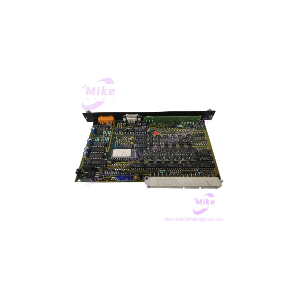
ECPNC3-0 PNC3
Key Technical Specifications
| Parameter | ECPNC3-0 Specification |
|---|---|
| Manufacturer | B&R |
| Part Number | ECPNC3-0 |
| Module Family | PNC3 |
| System Family | B&R MULTI |
| Module Type | Counter / Positioning Module |
| Encoder Inputs | 1 × incremental encoder |
| Counter Resolution | 24 bit |
| Encoder Supply | 24 VDC |
| Encoder Type | Externally supplied 24 VDC encoder |
| Encoder Signal Inputs | A, B, Reference / R |
| Encoder Input Isolation | Galvanically isolated through optocouplers |
| Analog Output | ±10 V |
| Analog Output Resolution | 11 bit |
| Input Frequency | 50 kHz in B&R’s current product listing |
| Historical Maximum Counting Frequency | 200 kHz, depending on documented operating configuration |
| Encoder Switching | Positive, negative, or push-pull |
| Application | Position detection, counting, positioning control |
| Hardware Status | Legacy / discontinued |
B&R’s current product search lists the ECPNC3-0 with a 50 kHz input frequency, while historical PNC3 documentation specifies a 200 kHz maximum counting frequency for the counter module. Because these figures appear in different B&R documentation contexts, confirm the applicable frequency specification against the machine configuration and module revision before using the maximum value for a production design.
Application Scenarios & Engineering Pain Points
Incremental Encoder Position Feedback
The most direct application is reading an incremental encoder and converting encoder pulses into a position/count value inside the B&R control system.
Typical machine functions include:
- Rotary position feedback
- Linear positioning
- Servo positioning feedback
- Conveyor position tracking
- Mechanical travel measurement
- Speed/count monitoring
- Indexing mechanisms
The module processes the encoder’s A/B signals and reference pulse, making it substantially more specialized than an ordinary digital input card.
Legacy Machine Repair
A common field problem is a machine that still runs correctly except for unreliable position feedback.
Before replacing the PLC rack, check:
- Encoder supply voltage.
- A/B signal integrity.
- Reference-pulse behavior.
- Encoder cable shielding.
- module diagnostics.
- Backplane connection.
- Application scaling and counter configuration.
Replacing a failed can preserve the existing control architecture when the rest of the B&R system remains operational.
Position-Control Applications
The ±10 V analog output makes the module suitable for control architectures where the calculated positioning/counting function must interface with an analog command path. B&R specifically identifies the module as a counter module for positioning applications.
Encoder Signal Troubleshooting
Intermittent position errors are not automatically proof of a failed .
If the machine loses counts only at higher speed, investigate:
- Encoder output frequency
- Cable capacitance
- Shielding
- Electrical noise
- Encoder supply stability
- A/B phase relationship
- Input threshold behavior
- Maximum applicable counting frequency
A position error that appears only during acceleration is often a signal-integrity problem rather than a simple software fault.
QA & Live Testing SOP
For a used , a basic power-on inspection is not enough.
Step 1 — Part Number Verification
Confirm:
- B&R manufacturer marking
- part number
- identification
- Hardware/revision markings
- Connector configuration
Do not substitute ECPNC3-1 simply because the mechanical format appears similar.
The historical B&R documentation differentiates and ECPNC3-1 by encoder interface architecture: is intended for externally supplied 24 VDC encoders, while ECPNC3-1 is designed for internally or externally supplied 5–15 VDC encoders with a different input configuration.
Step 2 — Physical Inspection
Check:
- PCB and housing
- Encoder connector
- Backplane connector
- Terminal contacts
- Signs of overheating
- Corrosion
- Cracked solder joints
- Damaged components
- Contamination
Step 3 — Controlled Power-Up
Install the module in a compatible B&R MULTI test environment.
Verify:
- Correct module startup
- Rack recognition
- Status indication
- No abnormal current behavior
- Stable encoder supply
Step 4 — Encoder Simulation
Use an appropriate incremental encoder simulator or controlled pulse generator.
Test:
- Channel A
- Channel B
- Reference pulse
- Forward counting
- Reverse counting
- Low-speed counting
- Representative higher-speed operation
Confirm that the controller receives stable count information.
Step 5 — Analog Output Verification
Verify the ±10 V output through controlled test conditions.
Check representative negative, zero, and positive output commands rather than testing only one point.
Step 6 — Isolation Verification
Where appropriate, verify the encoder-side isolation and signal behavior using equipment suitable for the module’s electrical design.
Step 7 — ESD Packaging
After testing:
- Protect the electronics in ESD-safe packaging.
- Protect the encoder connector.
- Prevent mechanical impact on the PCB.
- Use adequate cushioning for international shipment.
Field rule: If the module has not been tested with an actual encoder signal or suitable pulse simulation, it has not received a meaningful functional test.
Field Engineer’s Pitfall Guide
⚠️ Is Not the Same as ECPNC3-1
This is the first substitution issue to check.
is designed around externally supplied 24 VDC encoders. The historical B&R documentation specifies galvanically isolated encoder inputs for this configuration. ECPNC3-1 uses a different encoder voltage/input architecture.
Do not select the replacement based solely on the family name.
⚠️ Check the Encoder Supply
The -0 architecture connects the externally supplied 24 VDC encoder supply to the encoder interface.
Before installation, verify:
- Encoder nominal voltage
- Encoder current requirement
- Supply wiring
- Polarity
- Cable condition
A damaged encoder supply line can make a healthy appear defective.
⚠️ Do Not Ignore A/B Phase
If the count moves in the wrong direction, jumps unexpectedly, or loses position during reversals, check the A/B relationship.
Swapping A and B can change counting direction. A wiring fault affecting only one phase can create much more serious intermittent counting errors.
⚠️ Verify the Actual Frequency Limit
Available B&R documentation contains different frequency figures for depending on the document/context. B&R’s current product search lists 50 kHz, while the historical manual specifies 200 kHz maximum counting frequency.
For a high-speed application, verify the exact hardware revision and intended operating mode rather than designing around an unqualified maximum.





