


Description
B&R Automation 8LSA25R0060D000-0 Synchronous Servo Motor
Architect’s Product Breakdown
The B&R 8LSA25R0060D000-0 belongs to B&R’s 8LSA high-dynamic synchronous motor family. Engineered specifically for high-acceleration and high-precision applications—such as packaging equipment, CNC machinery, plastics processing, and robotics—this motor features high power density in a compact frame size.
When paired with B&R ACOPOS inverter drives (e.g., ACOPOSmicro, ACOPOSmulti, or ACOPOS P3), the integrated resolver feedback system transmits precise rotor position back to the drive. This allows the drive to automatically load the motor’s embedded electronic parameter chip (EnDat/Resolver setup) for plug-and-play commissioning without manual parameter entry.
The “8LSA” series utilizes rare-earth neodymium permanent magnets combined with optimized stator geometry to minimize cogging torque and heat dissipation. The IP65 enclosure rating protects the motor internals against dust and low-pressure water jets, making it suitable for tough industrial environments.
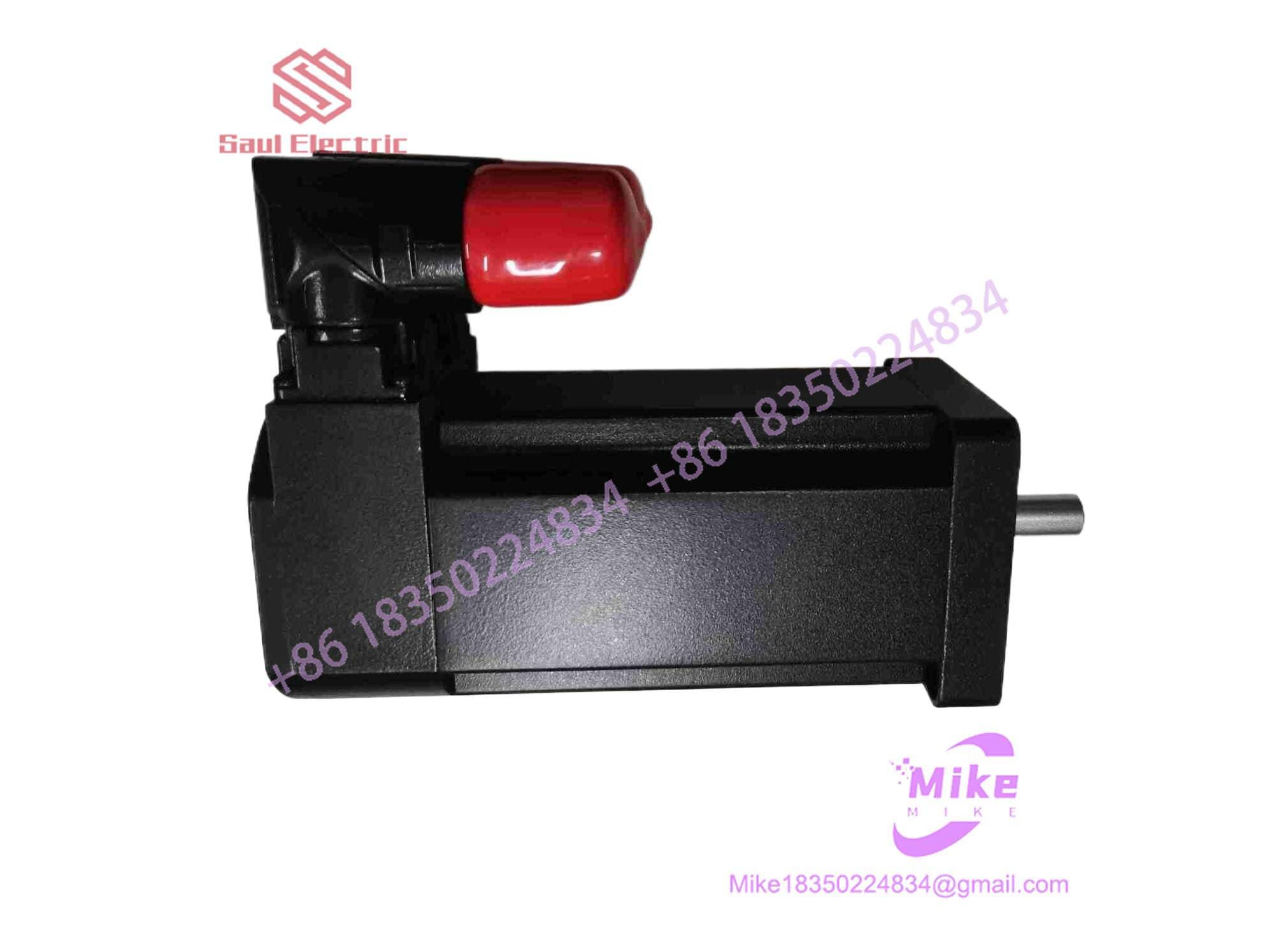
8LSA25R0060D000-0
Model Code Breakdown
8LSA 2 5 R 0060 D 0 0 0 -0
│    │ │ │ │    │ │ │ │  └── Special / Revision Designator
│    │ │ │ │    │ │ │ └───── Mechanical Options (0 = Standard)
│    │ │ │ │    │ │ └────── Holding Brake (0 = Without Brake)
│    │ │ │ │    │ └─────── Feedback System (D = Resolver)
│    │ │ │ │    └───────── Rated Speed (0060 = 6,000 RPM)
│    │ │ │ └────────────── Connection Type (R = Rotatable Angle Plug)
│    │ │ └──────────────── Stator Length (5 = Length 5)
│    │ └────────────────── Motor Frame Size (2 = Size 2 Flange)
│    └──────────────────── Motor Series (8LSA Synchronous Servo)
Key Technical Specifications
| Parameter | Specification |
| Motor Type | Permanent Magnet Synchronous Servo Motor (PMSM) |
| Frame Size | Size 2 (approx. 55–60 mm flange) |
| Stator Length | Length 5 |
| Rated Speed (n_N) | 6,000 RPM |
| Feedback Unit | Resolver (2-pole) |
| Shaft Design | Smooth Shaft (without keyway) |
| Holding Brake | None (Standard configuration) |
| Connector Orientation | Rotatable right-angle dual circular connectors |
| Degree of Protection | IP65 (excluding shaft passage without oil seal) |
| Cooling Method | Natural convection (Self-cooling) |
| System Compatibility | B&R ACOPOS, ACOPOSmicro, ACOPOSmulti, ACOPOS P3 |
Field Engineer’s Pitfall Guide
WARNING: Incorrect Resolver Shielding & Noise Interference
Resolver signals carry small analog sine/cosine voltages that are vulnerable to high-frequency EMI generated by the motor power cables. Always use original B&R pre-assembled double-shielded motor feedback cables (e.g., 8CR cables) and ground the cable shield 360° at the ACOPOS drive shield plate.
WARNING: Shaft Coupling Alignment on Smooth Shafts
Model code designation
0at the shaft option indicates a smooth shaft (no keyway). When installing rigid or flexible couplings, ensure the clamping element is torqued evenly to spec using a calibrated torque wrench. An under-torqued clamping hub will slip under high acceleration, causing position lag errors in Automation Studio.
WARNING: Over-tightening Cable Connectors
The motor utilizes rotatable right-angle speedtec/M23 circular connectors. While these allow 270° adjustment for easy cable routing, over-rotating them past their mechanical stops or applying excessive strain to the cable boot will break the internal stator wiring connections.
QA & Testing SOP
- Visual & Mechanical Inspection:
- Inspect motor housing, flange mounting face, and shaft for burrs, scratches, or corrosion.
- Rotate the shaft manually—it should turn smoothly without mechanical rubbing, bearing binding, or unusual noise.
- Verify connector pins are clean, straight, and free from oxidation or bent terminals.
- Winding Resistance & Insulation Test:
- Measure phase-to-phase resistance (U-V, V-W, W-U) using a calibrated milliohm meter; values across all three pairs must be balanced within \pm 2\%.
- Perform a Megger test between each power phase (U, V, W) and motor ground frame at 500 VDC. Insulation resistance must exceed 100 M\Omega.
- Resolver & Alignment Verification:
- Connect feedback tester to evaluate resolver primary and secondary winding impedances.
- Verify encoder/resolver phase offset angle relative to motor back-EMF to ensure correct commutation angle alignment.
- Bench Run Test with ACOPOS Servo Drive:
- Connect motor to an ACOPOS drive running B&R Automation Studio software.
- Read out the electronic nameplate data embedded in the motor feedback to confirm correct auto-identification.
- Perform a no-load velocity sweep up to 6,000 RPM while monitoring current draw, vibration levels, and bearing temperature stabilization.
- Packaging & ESD Handling:
- Wipe motor exterior with non-corrosive cleaner.
- Cap all connectors with protective dust covers.
- Package in heavy-duty foam-lined boxes with proper shaft protection before shipment.
Technical FAQ
What does the “R” in the model code stand for?
The “R” specifies the electrical connection style—in this case, rotatable right-angle circular connectors mounted on the motor housing, allowing you to direct motor power and feedback cables easily inside tight machine frames.
Can I replace an 8LSA25 motor with an 8LVA or 8JSA series motor?
Not directly without updating mechanical mounting and software drive configuration. While 8LVA and 8LSA share similar B&R controller ecosystems, their frame dimensions, torque-speed curves, and electrical parameters differ. Always verify flange geometry and Automation Studio motor configuration files first.
Does this motor come with an integrated holding brake?
No. The digit 0 in position 8LSA25R0060D000-0 indicates no mechanical holding brake is installed. If your vertical/z-axis load requires a brake to prevent falling on power loss, you need the motor variant equipped with an internal 24 VDC holding brake (indicated by 1 or 2 in the brake position code).
Which ACOPOS drive cable set should I use with this motor?
Use B&R standard motor power cable 8CM… and feedback cable 8CR… equipped with matching Speedtec/M23 connectors for Size 2 8LSA motors.





