

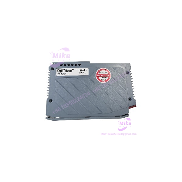
Description
B&R Automation 3NC154.60-2 | Positioning Module 3-Axis Controller
Dynamic Product Introduction
Complex high-speed positioning lines demand absolute synchronization across multiple mechanical axes to prevent tracking errors or mechanical binding. When aging counter cards suffer signal drift or fail to process high-frequency encoder pulses under heavy industrial noise, motion loops quickly lose position lock. The B&R Automation 3NC154.60-2 positioning module resolves these limitations by executing multi-axis pulse evaluation and closed-loop position tracking with exceptional hardware precision.
Instead of bogging down the central CPU with raw interrupt processing, the B&R Automation 3NC154.60-2 handles multi-axis counting and fast digital triggering locally on the module layer. Supporting both incremental and SSI absolute encoders up to 150 kHz, this unit interfaces smoothly with diverse feedback devices. Integrating the B&R Automation 3NC154.60-2 into your PLC backplane ensures deterministic position capture, allowing high-throughput machinery to maintain tight tolerances during continuous cyclic operation.
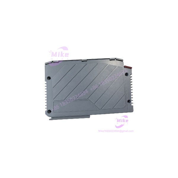
3NC154.60-2
Key Technical Specifications
- Module Function: 3-Axis Positioning and Counter Module
- Encoder Compatibility: Incremental and SSI absolute encoders
- Max Input Frequency: Up to 150 kHz
- Counter Resolution: 32-bit internal counter size
- Digital Inputs (DI): 5 isolated 24 VDC inputs
- Digital / Relay Outputs: 1 relay output (24 VAC/DC, 1 A rating)
- Analog Output (AO): 1 channel (\pm 10 V, 12-bit digital converter resolution)
- Encoder Power Supply: 24 VDC internal backplane-derived supply
- Operating Temperature: 0 °C to +55 °C ambient range
- Physical Mounting: Standard B&R modular backplane slot rack
- Weight: Approx. 0.68 kg (1.5 lbs)
Global Sourcing & Live-Test SOP (Transparency Core)
Procuring surplus or replacement automation hardware like the B&R Automation 3NC154.60-2 requires a strict verification protocol to guarantee that internal counter chips and optical isolation barriers have not suffered electrical damage.
- Inbound Inspection: Incoming modules undergo microscopic examination for terminal pin corrosion, PCB flex stress, and anti-tamper security label authenticity. Part numbers are checked against factory distribution records to screen out unverified grey-market stock.
- Component Testing: Technicians use high-precision multimeters and logic analyzers to test optical isolation channels, internal voltage regulators, and relay output continuity.
- Live Test Bench Simulation: The unit is slotted into an authentic B&R modular PLC rack powered by regulated 24 VDC rails. A high-frequency signal generator simulates multi-axis incremental and SSI encoder streams to verify pulse counting accuracy across all channels.
- Burn-In Cycle: Modules undergo a 24-hour continuous thermal soak test inside an environmental chamber to flush out latent component degradation or solder joint fractures under operational load.
- Final Preparation: Configuration registers are cleared to factory default parameters, diagnostic logs are archived, and the hardware is sealed inside thick anti-static ESD shielding bags with active desiccant packs.
The Field Engineer’s Pitfall Guide
- ❗ Mismatched encoder voltage supply rails can blow input receiver chips: Connecting a 5 VDC differential encoder to a channel configured for a 24 VDC power supply without proper level shifting will instantly destroy the module’s input transceiver gates. Always verify encoder voltage specifications before landing field wiring.
- ❗ Improper shield grounding on encoder cables introduces high-speed counting jitter: Leaving encoder cable braided shields floating instead of terminating them cleanly to the cabinet ground bar allows variable frequency drive (VFD) noise to corrupt pulse trains. I’ve seen positioning loops fault out mid-cycle simply because electromagnetic interference triggered ghost counts on high-frequency lines.
- ❗ Forced insertion into an energized backplane damages bus pins: Sliding the module into an active rack rack without isolating system power risks electrical arcing across the multi-pin bus connector, which can ruin both the card and the backplane slot. Always power down the enclosure before performing hardware swaps.
Intent-Driven FAQ
Can I use the B&R Automation 3NC154.60-2 with both incremental and absolute encoders?
Yes. The module supports flexible configuration parameters in the B&R programming environment, allowing you to interface with standard incremental quadrature encoders as well as synchronous serial interface (SSI) absolute encoders.
Will replacing this module require updating my PLC project software?
If you are replacing a failed unit with an exact hardware revision matching the original part number, the control program will recognize the module via the backplane automatically without requiring software code modifications.
What causes unexpected position drift during high-speed axis travel?
Position drift is typically caused by loose encoder terminal connections, severe electrical noise coupling on unshielded signal lines, or improper grounding of the encoder cable shield.
How do I reset the module to factory default configurations?
Module parameters are managed entirely through the system software project configuration downloaded from the central PLC CPU. Re-downloading the valid project configuration overwrites local parameters and restores default states.
Are replacement pluggable terminal blocks available if my connectors are damaged?
Yes, matching pluggable screw or clamp terminal blocks can be sourced through industrial automation distributors, though using OEM-specified connectors ensures secure mechanical locking under heavy machine vibration.





