


Description
B&R 8V1090.00-2 | High-Output Servo Drive 400-480 VAC
Dynamic Product Introduction
The 8V1090.00-2 sits in the heavy-duty tier of B&R’s ACOPOS 1000 servo drive line. Built to power high-torque Size 5 and Size 6 motor frames across demanding packaging machines, CNC rotary tables, and high-speed material handling axes, this unit packs significant current delivery capability into a rigid, panel-mountable chassis.
Powered by a 3\times 400–480 VAC line supply, the drive supplies 18.0 A of continuous output current with peak output capabilities reaching up to 36.0 A for short-duration acceleration spikes. Its modular front enclosure features standard option slots for fieldbus cards (POWERLINK AC114, CANopen AC110) and motor feedback interface cards (AC122 Resolver, AC130 EnDat), enabling flexible software configuration in Automation Studio without changing base drive hardware.
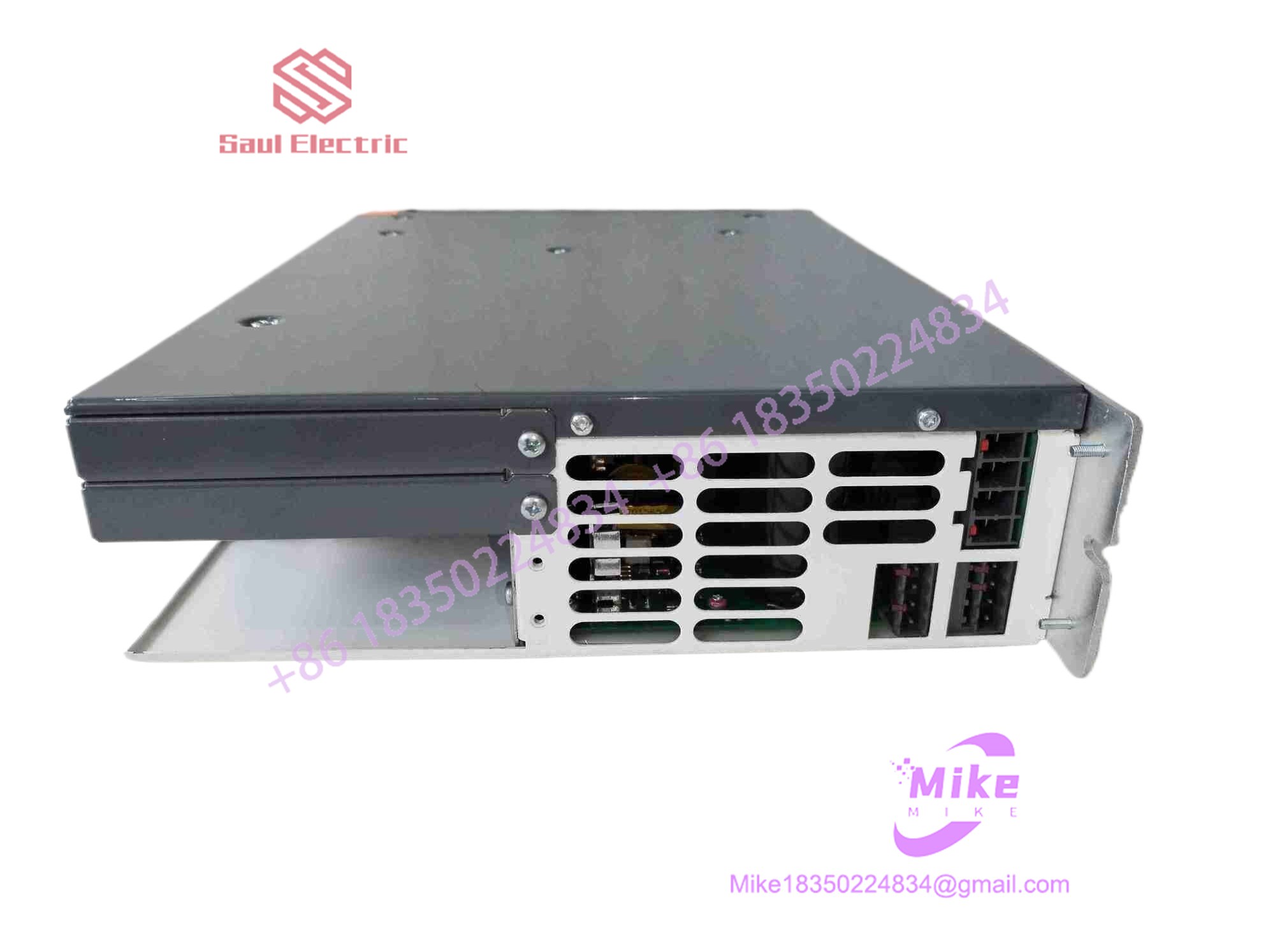
8V1090.00-2
Key Technical Specifications
| Parameter | Specification | Field Note / Operational Limit |
| Mains Input Voltage | 3\times 400 VAC to 480 VAC (\pm 10\%) | 50/60 Hz supply line connection |
| Continuous Current (I_N) | 18.0 A RMS | Continuous nominal rating at 8 kHz switching frequency |
| Peak Current (I_{\max}) | 36.0 A RMS | Transient peak output capacity (up to 5 seconds) |
| Power Consumption | ~14.0 kVA | Apparent output power capacity |
| 24V Control Power | 24 VDC (\pm 15\%) | External logic supply required for onboard control boards |
| DC Bus Voltage | 560–800 VDC | Internal DC link created from rectified mains line |
| Option Slots | 3 Expansion Card Slots | Accommodates network cards (POWERLINK, CAN) & feedback cards (Resolver, EnDat) |
| Braking Resistor | Integrated / External Terminals | Built-in braking circuit with terminals for external heavy-duty braking resistors |
| Cooling Method | Forced Fan Cooling | Internal heat sink fan; requires minimum 100mm vertical clearance top/bottom |
Global Sourcing & Live-Test SOP (Transparency Core)
Sourcing higher-current servo drives requires strict component checks—a drive with failing DC link capacitors or damaged output IGBT gates can cause immediate system trips under heavy acceleration. Every unit undergoes our standard multi-point verification protocol before shipment:
- Inbound Visual & Component Inspection:
We inspect the housing, power terminals, and option card bus backplane pins. Internal electrolytic DC bus capacitors are tested for ESR (Equivalent Series Resistance) and capacitance drift.
- 24V Control Board & Fieldbus Test:
24 VDC logic power is applied to confirm CPU boot sequencing, status LED indicators, and communications via network expansion cards (
AC114POWERLINK /AC110CANopen) in Automation Studio. - Full-Power Dynamic Load Test:
The drive is powered with a 400 VAC three-phase line supply and interfaced with an 8MSA series servo motor under dynamic brake load. The unit runs a multi-hour trajectory test to monitor:
- IGBT thermal equilibrium under continuous 18 A current draw.
- PWM phase switching balance across terminals U, V, W.
- Regenerative braking chopper circuit activation during dynamic braking.
- ESD Packaging & Preparation:
Option slot protective covers are verified and main terminal block screws secured. The unit is wrapped in static-shielding film and cushioned inside custom high-density foam packaging.
The Field Engineer’s Pitfall Guide
- ❗ Never Apply Mains Line Power Without Active 24V Logic Supply:
Always verify that the 24 VDC logic power supply is connected and fully stable before applying 400/480 VAC mains power. Applying main line voltage to an ACOPOS drive without active control logic can trigger DC bus charging circuit faults or damage the pre-charge resistors.
- ❗ DC Bus Capacitors Hold High Voltage After Disconnection:
After disconnecting mains power, the internal DC link capacitors retain dangerous high voltage (>700 VDC) for several minutes. Always measure the voltage across terminals
DC+andDC-with a calibrated meter to verify it has dropped below 50 VDC before servicing wiring or removing option cards. - ❗ Hot-Plugging Option Cards Damaging Backplane Electronics:
Never insert or remove expansion cards (e.g.,
AC114,AC122,AC130) while 24 VDC or main power is connected to the drive. Inserting cards on a live drive will burn out internal backplane bus chips, making the expansion slot unusable.
Intent-Driven FAQ
How does the 8V1090.00-2 compare to smaller ACOPOS 1000 models?
Model numbers designate the continuous current output within the ACOPOS 1000 product line:
- 8V1010.00-2: Continuous current of 2.2 A RMS.
- 8V1045.00-2: Continuous current of 8.8 A RMS.
- 8V1090.00-2: Continuous current of 18.0 A RMS (designed for mid-to-heavy industrial loads).
Does the 8V1090.00-2 come with built-in motor feedback connectors?
No. Base ACOPOS drive units use modular slots for feedback interfaces. To read motor position signals (Resolver, EnDat, or Incremental encoder), you must install a matching feedback option card—such as an AC122 (Resolver) or AC130 (EnDat)—into option slot 2 or 3.
Can I run the 8V1090.00-2 on a single-phase AC power input?
No. The 8V1090.00-2 requires a three-phase 400–480 VAC line supply to generate the proper DC bus voltage (~560–700 VDC). Attempting to run on a single-phase supply will cause continuous undervoltage faults (Undervoltage DC Bus Error 6019).
What does error code 6019 indicate on an ACOPOS drive?
Error 6019 signifies a DC Bus Undervoltage condition. It occurs when incoming 400 VAC line power drops, a supply fuse trips, or the internal pre-charge relay fails to close.
How can I verify that a replacement 8V1090 drive is unused OEM stock?
Inspect the heavy power terminal block screws, mounting plate flanges, and gold option card slot pins. Unused factory-sealed units show no tool torque marks on terminal screws, zero mounting scratch marks on the rear heat sink flange, and pristine connector pins without insertion tracking.





