


Description
B&R 8MSA3L.R0-30 | Size 3 Frame 1.2 Nm Resolver
Dynamic Product Introduction
Operating automated assembly cells under harsh shop-floor conditions exposes delicate optical feedback systems to constant vibration and oil vapor contamination. B&R built the 8MSA3L.R0-30 specifically to survive those unforgiving industrial spaces. By pairing an extended Size 3 stack length (“L” variant) with a heavy-duty analog resolver (R0), this motor delivers roughly 1.20 Nm of continuous stall torque while staying virtually immune to the shock loads that shatter glass-scale optical encoders.
When upgrading legacy machinery or swapping out worn units, the difference shows up immediately in thermal durability and drive synchronization. Connected to an ACOPOS drive, the resolver feedback loop provides smooth, sinusoidal commutation right down to zero speed. Automation Studio manages the motor’s operating profile via standard library definitions, keeping axis commissioning straightforward and preventing current loop instability.
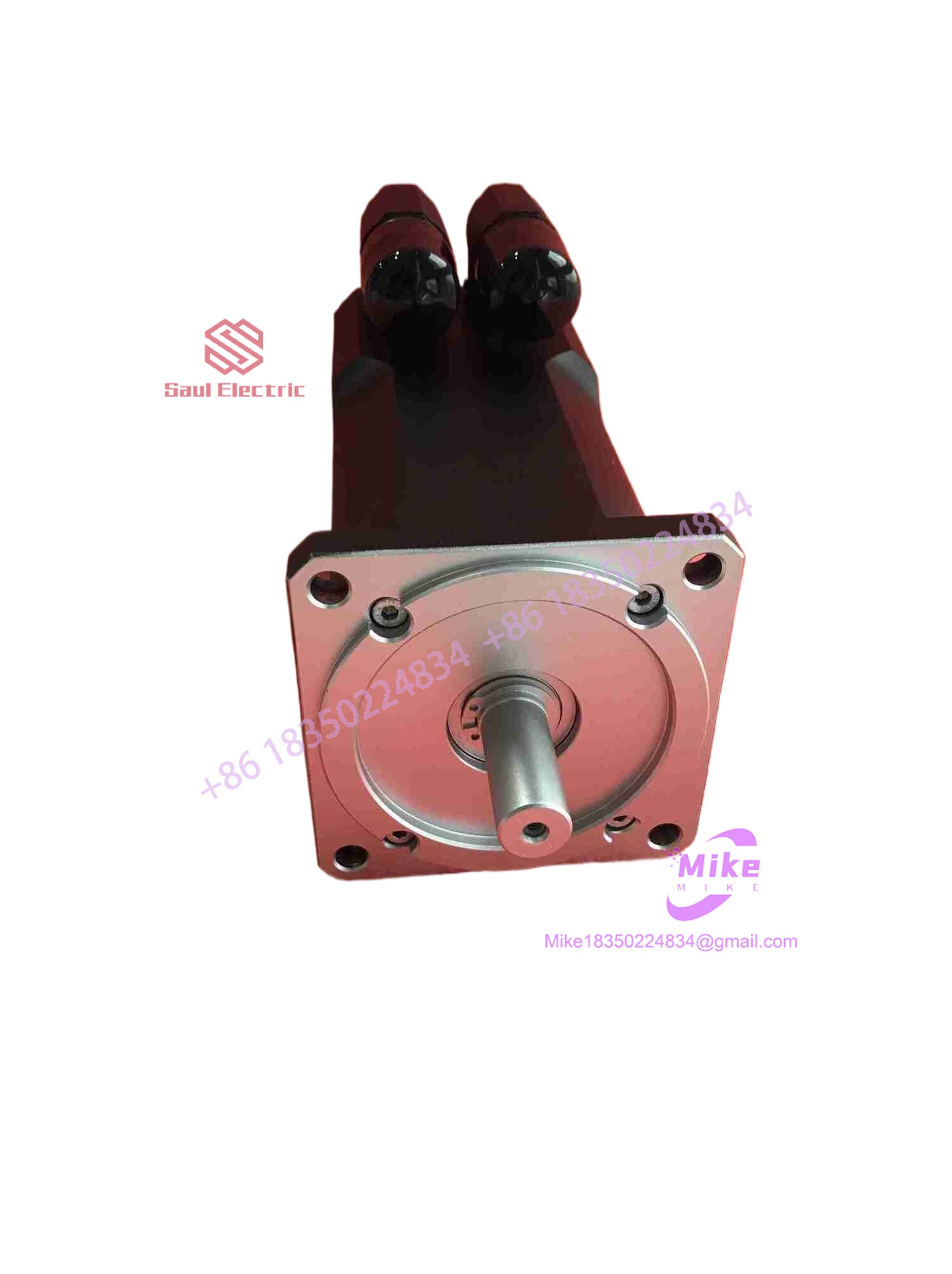
8MSA3L.R0-30
Key Technical Specifications
| Parameter | Specification | Field Note / Operational Limit |
| Rated Speed | 3000 RPM | Continuous operational speed limit at nominal bus voltage |
| Stall Torque (M_0) | ~1.20 Nm | Continuous torque rating (\Delta T = 100 K) |
| Peak Torque (M_{\max}) | ~4.80 Nm | Short-duration acceleration transient limit |
| Feedback System | Analog Resolver (R0 Variant) | Electromagnetic transformation feedback, high vibration tolerance |
| Flange Size | Size 3 (~70mm Flange) | Compact mounting footprint for tight multi-axis toolheads |
| Protection Rating | IP65 | Housing sealed against industrial dust and splash oil |
| Connection Type | Dual SpeedTEC / Intercontec | 90-degree rotatable circular quick-lock connectors |
| Cooling Method | Natural Convection | Requires minimum 30mm surrounding air gap for heat dissipation |
| Thermal Protection | Integrated Thermal Sensor | Monitored directly via internal feedback wiring loop |
Global Sourcing & Live-Test SOP (Transparency Core)
Procuring replacement surplus motion hardware demands rigorous bench testing—installing a motor with degraded resolver bobbins or bearing race pitting will lead to immediate axis jitter under load. Here is our exact multi-stage quality control protocol before any stock leaves our ESD workspace:
- Inbound Mechanical Inspection:
We clamp the shaft under digital dial indicators to verify radial and axial runout remain within factory spec (<0.015mm). Serial nameplates are cross-referenced against B&R database records to catch counterfeit relabeling.
- ACOPOS Bench Simulation Setup:
The unit mounts to a dedicated test bench connected to an authentic ACOPOS drive channel running B&R Automation Studio.
- Diagnostic Test Execution:
- Resolver Phase Handshake: We monitor resolver excitation carrier waves on an oscilloscope to confirm zero signal distortion and verify correct transformation ratios across 360^\circ.
- Full-Speed Dynamic Test: The unit undergoes a continuous 3-hour velocity profiling run reaching 3000 RPM, tracking real-time winding temperature stabilization and bearing noise signatures.
- Dielectric Megger Test: A 1000V DC surge test across phase-to-phase and phase-to-ground paths guarantees zero insulation breakdown.
- Final ESD Packaging:
Shaft extensions receive protective grease and caps. The complete assembly is wrapped in static-shielding film and cradled in custom high-density foam packaging.
The Field Engineer’s Pitfall Guide
- ❗ Resolver Null-Point Offset Errors from End-Cap Tampering:
Never loosen or adjust the rear end-cap assembly on an
R0motor variant. On B&R motors, the physical alignment of the resolver stator relative to the rotor’s magnetic poles is factory-pinned. Shifting the resolver body even by a fraction of a millimeter alters the commutation angle, causing the ACOPOS drive to draw massive current spikes or throwCommutation Angle Error 9005immediately upon enabling power. - ❗ Forcing Connector Rotation Under Cable Strain:
While the SpeedTEC right-angle circular connectors swivel for flexible cable routing, attempting to turn the connector housing while the mating cable plug is locked down will twist and shear internal stator lead wires. Always unlock and remove the mating cable plug completely before adjusting the connector orientation.
- ❗ Shaft Coupling Damage from Direct Mechanical Impact:
Because Size 3 shafts are precision-ground, hammering gear couplings or timing pulleys onto the shaft extension will collapse internal ball bearing races and fracture the resolver winding bobbin positioned directly behind the rear bearing. Always draw couplings on smoothly using a threaded puller tool anchored in the shaft’s tapped center hole.
Intent-Driven FAQ
Will my ACOPOS drive automatically configure itself when I install this motor?
If your system uses standard ACOPOS motor database entries in Automation Studio, selecting the model code 8MSA3L.R0-30 automatically assigns matching current limits, resolver excitation frequencies, and velocity loop gains.
What is the primary advantage of resolver feedback (R0) over optical encoders (E0/EB)?
Resolver feedback (R0) relies on electromagnetic induction rather than delicate glass optical disks. Resolvers withstand extreme mechanical shock, high ambient temperatures, and heavy machine vibration far better, making them vastly more reliable in aggressive production environments.
Can I replace an 8MSA3L.R0-30 with an optical encoder motor like the 8MSA3L.E0 series?
Not without modifying your drive configuration and cabling. Optical EnDat encoders (E0) require digital serial data communication lines and a different pinout configuration at the ACOPOS drive compared to analog resolver excitation channels. Your Automation Studio project hardware tree must match the exact feedback variant installed.
What should I check if Automation Studio throws a motor overtemperature error upon installation?
First, check the feedback cable connection. The motor’s internal thermal sensor signal routes through dedicated pins inside the resolver connector. An unseated connector or pushed-back pin creates an open circuit, which the drive interprets as an extreme thermal fault above 150^\circC.
How can I confirm if a replacement 8MSA3L motor is factory unused?
Inspect the mounting flange face, shaft keyway, and gold connector pins. Unused factory-sealed stock exhibits zero bolt compression rings or paint scraping around the flange holes, unmarred shaft surfaces, pristine gold connector pins without insertion tracking, and original protective caps intact over the shaft extension and electrical connectors.





