


Description
B&R 8LSA35.E2060D000-0 | 8LSA Servo Motor with Holding Brake
Architect’s Product Breakdown
The B&R 8LSA35.E2060D000-0 belongs to B&R’s 8LSA high-dynamic synchronous motor family. Engineered specifically for demanding multi-axis applications—such as packaging machinery, CNC systems, robotics, and high-speed material handling—this motor combines low rotational inertia with high continuous torque output.
The E2 code designates an inductive multi-turn absolute encoder (EnDat protocol). The embedded electronic parameter chip automatically transmits all motor parameters, limits, and thermal calibration data to the ACOPOS servo drive upon startup. This enables immediate plug-and-play commissioning without manual parameter setup in B&R Automation Studio.
Unlike non-braked variants, this model integrates a built-in 4.0 Nm 24 VDC mechanical holding brake. This holds vertical or inclined axes securely when drive power is interrupted, preventing back-driving and equipment damage. The motor features an 80 mm centering flange (j6 fit), self-cooling construction (Type A), and swiveling angled circular connectors for flexible cable routing inside tight enclosures.Model Code Breakdown
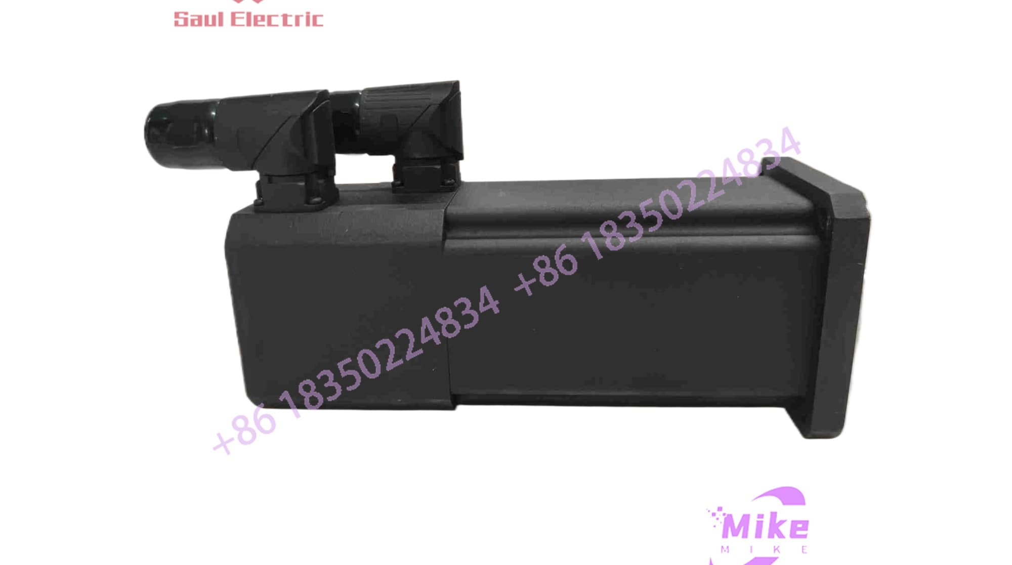
8LSA35.E2060D000-0
Model Code Breakdown

8LSA 3 5 . E2 060 D 0 0 0 -0
│    │ │   │  │   │ │ │ │  └── Generation / Revision Designator (-0 Generation)
│    │ │   │  │   │ │ │ └───── Special Options (0 = Standard)
│    │ │   │  │   │ │ └────── Mechanical Option (0 = With 24V holding brake)
│    │ │   │  │   │ └─────── Shaft Design (D = Smooth shaft, d=14mm k6)
│    │ │   │  │   └───────── Rated Speed (060 = 6,000 RPM)
│    │ │   │  └───────────── Connection & Encoder (E2 = Swivel connector, EnDat multi-turn absolute)
│    │ │   └──────────────── Stator Length (5 = Length 5)
│    │ └──────────────────── Motor Frame Size (3 = Size 3 Flange, 80mm centering)
│    └────────────────────── Motor Series (8LSA Synchronous Servo)
Key Technical Specifications
| Parameter | Specification |
| Motor Type | Permanent Magnet Synchronous Servo Motor (PMSM) |
| Frame Size / Centering | Size 3 / 80 mm Centering (j6 fit) |
| Stator Length | Length 5 |
| Stall Torque (M_0) | 2.30 Nm |
| Nominal Speed (n_N) | 6,000 RPM |
| Number of Pole Pairs | 2 Pairs (4 Poles) |
| Feedback Unit | EnDat Multi-Turn Absolute Encoder (32-line) |
| Holding Brake | Yes (4.00 Nm Holding Torque) |
| Shaft Design | Smooth Shaft (d=14 mm k6, without keyway) |
| Connector Type | Dual Speedtec circular connectors, angled swivel |
| Nominal Bus Voltage | 560 VDC |
| Degree of Protection | IP64 (without shaft oil seal) |
| Drive Compatibility | B&R ACOPOS, ACOPOSmulti, ACOPOS P3 |
Field Engineer’s Pitfall Guide
WARNING: Holding Brake is NOT a Dynamic Service Brake
The integrated 4.0 Nm holding brake is a spring-applied, electromagnetically released safety device intended strictly for static holding. Engaging the brake repeatedly while the shaft is spinning at 6,000 RPM will burn the friction lining, leading to loss of holding torque on vertical axes.
WARNING: 24 VDC Holding Brake Voltage Drop
Long motor power cables introduce a DC voltage drop on the 24 VDC brake supply lines. If the supply voltage at the motor drops below 21.6 VDC, the electromagnetic coil may fail to fully release, causing the brake pads to drag, overheat, and trip the ACOPOS drive on overcurrent.
WARNING: Shaft Coupling Alignment on Smooth Shafts
The D shaft design is a smooth cylindrical surface without a keyway. Clamping hubs or shrink discs must be thoroughly degreased before installation and torqued to specification using a calibrated torque wrench. Slippage under dynamic acceleration will result in immediate position tracking errors in Automation Studio.
QA & Testing SOP
- Visual & Mechanical Inspection:
- Inspect housing, mounting flange, and smooth shaft surface for scores, corrosion, or mechanical damage.
- Mechanically verify the holding brake: with 0V applied, the shaft should remain locked. Apply 24 VDC to release the brake and verify smooth, noise-free manual shaft rotation.
- Confirm the swivel connector base rotates smoothly without straining internal wiring harness leads.
- Winding Resistance & Insulation Diagnostics:
- Measure phase-to-phase winding resistance (U-V, V-W, W-U) using a calibrated milliohm meter; values must be balanced within \pm 2\%.
- Perform a 500 VDC Megger test between motor power lines and motor chassis earth; insulation resistance must exceed 100 M\Omega.
- EnDat Feedback & Brake Functional Test:
- Connect motor to an ACOPOS test bench running B&R Automation Studio.
- Confirm auto-identification of motor nameplate parameters via the EnDat electronic parameter chip.
- Test automatic brake release timing sequence during drive enable/disable cycles.
- Dynamic Closed-Loop Test Run:
- Run a smooth velocity ramp sweep up to 6,000 RPM.
- Measure phase currents, check feedback stability, verify vibration spectrum, and confirm thermal equilibrium during continuous running.
- ESD Cleaning & Storage Preparation:
- Install protective plastic caps over the smooth shaft and Speedtec connectors.
- Wrap in ESD anti-static bags containing fresh desiccant and pack securely inside heavy-duty foam containers.
Technical FAQ
What is the difference between “-0” and “-3” revision models?
The -0 trailing suffix denotes B&R’s earlier generation 8LS motor hardware. The newer -3 revision variants feature updated connector designs, streamlined single-cable hybrid options (e.g., DA/DB codes), and revised encoder revisions, but both generations maintain identical flange mounting geometry and shaft dimensions.
Is this motor equipped with a shaft oil seal?
No. The standard 8LSA35.E2060D000-0 is rated IP64 and does not include a shaft passage oil seal. If installing the motor directly into a wet gearbox environment, an external oil seal or a model variant with an integrated shaft seal is required.
Does this motor retain its position after power loss?
Yes. The E2 feedback system is a multi-turn absolute encoder (EnDat). It keeps track of absolute position over multiple revolutions without requiring homing routines or external backup batteries upon power-up.
What supply voltage is required to release the holding brake?
The internal brake operates on 24 VDC (+6% / -10%). Ensure the power supply feeding the ACOPOS brake output channels can supply sufficient inrush current to fully disengage the coil.





