


Description
B&R 7DM465.7 | 8 DI 24VDC 8 DO 0.5A Module
Architect’s Product Breakdown
The B&R 7DM465.7 (DM465) is a high-density combination I/O expansion module engineered for the legacy B&R SYSTEM 2003 control platform. By packing 8 digital inputs and 8 digital transistor outputs onto a single screw-in card footprint, it solves spatial panel constraints in mid-tier OEM machinery like injection molding cells, pick-and-place manipulators, and automated conveyor lines.
The 8 digital input channels accept standard 24 VDC industrial signal levels from limit switches, proximity sensors, and photoelectric eyes with an integrated 1 ms hardware input filter to reject electrical switching noise. The output section features 8 high-side switching transistor channels rated at 0.5 A continuous current per output at 24 VDC. Each output driver incorporates electronic short-circuit and thermal overload protection, preventing an accidental field wiring fault from destroying the internal silicon switching bridges.
From an architecture perspective, the 7DM465.7 allows system integrators to minimize backplane slot consumption when controlling localized machine sub-assemblies that require a balanced 1:1 input-to-output ratio. However, because both input sensing circuits and output power stages share a compact terminal block interface, field engineers must strictly separate logic ground returns from heavy actuator load return paths to avoid ground-bounce issues during simultaneous multi-channel switching.
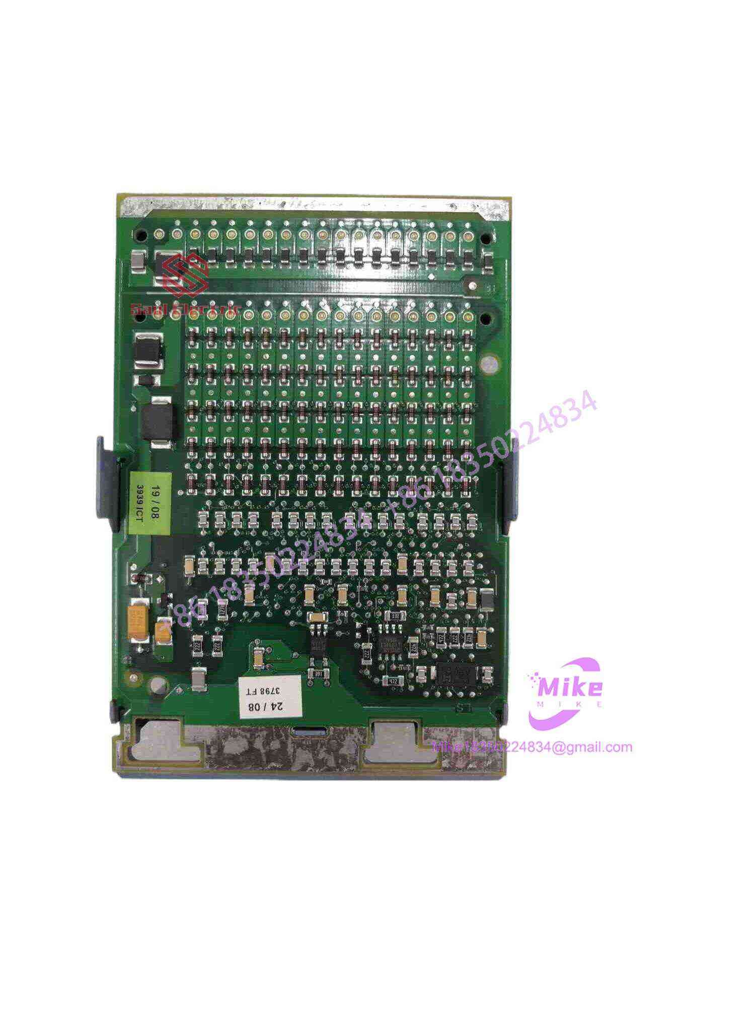
7DM465.7
Key Technical Specifications
| Parameter | Specification |
|---|---|
| Digital Inputs | 8 Channels (24 VDC, Sink/Source depending on wiring) |
| Input Current | Typ. 4 mA to 6 mA at 24 VDC per channel |
| Input Filter Delay | Typ. 1.0 ms |
| Digital Outputs | 8 Transistor Channels (High-side switching) |
| Output Voltage Range | 24 VDC nominal (-15% / +20%) |
| Output Current Rating | 0.5 A max per channel (Total module current max 4.0 A) |
| Short-Circuit Protection | Integrated electronic current limiting & thermal shutdown |
| Isolation | Optocoupler isolation (Field-to-Backplane logic) |
| Status Display | Dual-row LED status indicators (Channel ON/OFF) |
| Backplane Power Draw | Typ. 0.8 W from 5 VDC system bus |
| Certifications | CE, UKCA, cULus HazLoc Class I Div 2 |
| Operating Temperature | 0°C to +60°C |
Field Engineer’s Pitfall Guide
WARNING: Inductive Back-EMF Spikes on Unsuppressed Solenoids Although the transistor outputs feature internal clamping diodes for low inductive loads, driving unsuppressed large DC solenoid valves or motor contactor coils directly from the 0.5 A outputs will cause repetitive voltage spikes that degrade the switching transistors over time. Always wire flyback suppressors (1N4007 diodes or RC suppression networks) directly across the terminals of all inductive loads connected to the 7DM465.7.
WARNING: Shared External 24V Field Power Rail Fusing The transistor output section requires external 24 VDC to feed the high-side drivers. If an external short circuit occurs across an un-fused field wire, the internal current-limiting circuit will clamp the fault, but prolonged thermal saturation can stress adjacent input optocouplers. Install a fast-acting 4.0 A inline fuse on the incoming 24 VDC field supply line feeding the module’s output power terminals.
WARNING: Terminal Block Torque and Guide Pin Alignment When inserting this module into a SYSTEM 2003 expansion slot or CPU base bay, pushing hard against an unaligned multi-pin backplane connector will bend the delicate gold pins. Slide the card smoothly along the plastic side rails and hand-tighten the retention screws; never use electric screwdrivers to force the board home.
QA & Testing SOP
- Visual & Mechanical Verification:
- Inspect module housing for cracks, stress fractures, or broken mounting tabs.
- Verify terminal block screw threads and examine gold backplane pins for oxidation or pin deflection.
- Cross-check OEM serial numbers and firmware revision stickers against test logs.
- Dielectric Isolation & Leakage Test:
- Perform a 500 VDC megohmmeter insulation check between the field terminal contacts and backplane logic pins (>100 MΩ required).
- Verify zero short circuits between adjacent digital output power traces.
- Functional Input & Output Dynamic Bench Test:
- Mount module onto an active B&R SYSTEM 2003 test rack loaded with Automation Studio diagnostic software.
- Drive all 8 inputs through automated 24 VDC signal switching cycles; record logic response times and verify physical LED synchronization.
- Load each of the 8 output channels with a 0.5 A resistive load (~48 Ω); verify continuous current capacity and thermal stability under full load.
- Short-Circuit & Protection Circuit Trigger Test:
- Momentarily ground an active 0.5 A output channel to verify that electronic short-circuit protection trips instantly without damaging the switching stage.
- Run a 12-hour thermal burn-in cycle in a 50°C test chamber under full continuous I/O cycling.
- Final Preservation & ESD Packaging:
- Clean board contacts with isopropyl alcohol solution.
- Enclose in static-shielding ESD bags with moisture-absorbing desiccant before final warehousing.
Technical FAQ
Can I mix different power supplies for the input and output circuits on the 7DM465.7?
Yes. The digital inputs use optocoupler isolation to separate field sensing loops from internal backplane logic. You can use separate 24 VDC power supplies for the input sensor field loop and the output transistor load supply, provided the respective 0 VDC reference potentials are properly wired according to your machine’s grounding topology.
Is the 7DM465.7 hot-swappable while the PLC is powered?
No. The B&R SYSTEM 2003 backplane is not designed for hot-swapping expansion modules. Inserting or removing the 7DM465.7 while the system 24 VDC power is active risks bus communication corruption, transient electrical spikes, and potential hardware damage to both the module and the base rack.
What happens if an output channel experiences an overload or short circuit?
The individual output driver enters a thermal current-limiting mode to protect its internal circuitry. The output channel turns OFF or restricts current flow until the short circuit is removed and the transistor cools down. Once the fault condition is cleared, normal operation resumes without requiring a full PLC power cycle.
Can I parallel two output channels to drive a single 1.0 A load?
No. Paralleling output channels on the 7DM465.7 is not recommended. Differences in transistor switching times (even a few microseconds) will cause the faster channel to temporarily carry the full 1.0 A load, triggering its short-circuit protection and leading to erratic switching behavior. Use an external interposing relay for loads exceeding 0.5 A.





