Description
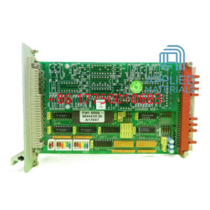
AMAT 0010-44213 | Refurbished Cleanroom Ready Stock
Dynamic Product Introduction
Drift in non-contact temperature measurement during a 1000°C spike anneal can ruin an entire lot of 300mm wafers before the tool triggers a software fault. Because Rapid Thermal Processing (RTP) relies on precise closed-loop power modulation across tungsten-halogen lamp arrays, a degrading pyrometer probe leads directly to off-target sheet resistance and lattice defects. The Applied Materials 0010-44213 pyrometer probe assembly resolves this temperature-sensing instability, collecting real-time infrared emission from the wafer backside with minimal optical distortion.
Honestly, trying to stretch the lifespan of a clouding or thermally degraded optical lightpipe in a Radiance chamber is a risky move for any fab maintenance team. Machined to fit AMAT 300mm Radiance and Vantage RTP chamber bases, the 0010-44213 uses high-purity optical components to maintain calibration stability across steep ramp rates exceeding 100°C per second. Replacing an aging sensor assembly restores true emissivity feedback, eliminating thermal non-uniformities without requiring manual software offsets.
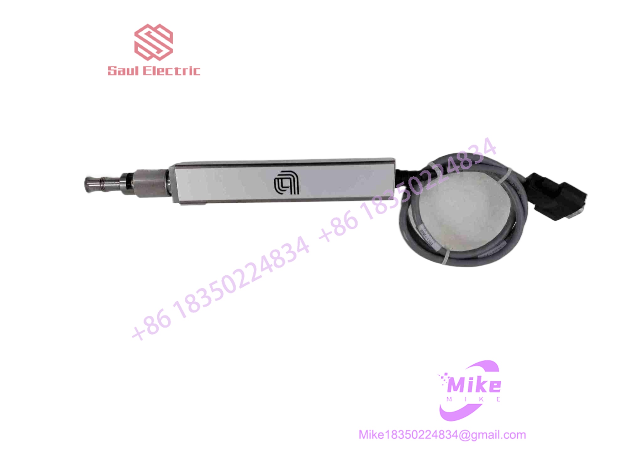
0010-44213
Key Technical Specifications
| Parameter | Specification Details |
| Model Part Number | 0010-44213 |
| Associated PCB/Assembly | 0150-00743 / QCM Board Interface |
| Manufacturer | Applied Materials (AMAT) |
| Tool Compatibility | 300mm Radiance / Vantage RTP Systems |
| Measurement Method | Non-Contact Optical Infrared Pyrometry / Emissometry |
| Wavelength Range | Near-Infrared Spectrum (Process Optimized) |
| Operating Temperature Range | Ambient to +1200°C Wafer Temp Measurement Envelope |
| Cooling Requirement | Water/Chiller-Cooled Base Mount & Purge Gas Channel |
| Fiber-Optic Interface | Precision SMA / Fiber Bundle Connection |
| Vacuum Rating | High-Vacuum O-Ring Flange Sealed (< 1 \times 10^{-8} mbar·L/s) |
| Housing Material | Passivated Stainless Steel & Optical Sapphire/Quartz Lens |
Global Sourcing & Live-Test SOP (Transparency Core)
Deploying optical measurement hardware into a high-temperature semiconductor tool requires comprehensive physical and spectral verification. Every AMAT 0010-44213 pyrometer assembly sourced through our refurbishment channels undergoes a strict four-stage diagnostic sequence prior to shipment.
Inbound Inspection & Optical Integrity
Technicians perform microscopic evaluations of the sapphire tip, fiber entry port, and mounting threads to verify that no micro-fractures, clouding, or process byproduct deposits exist on the optical path.
Dark Current & Light Transmission Calibration
The assembly is connected to an optoelectronic analyzer to verify signal throughput:
- Dark Current Noise Floor: Measured in an isolated dark chamber to verify sensor amplifier signal-to-noise ratios.
- Spectral Response Check: Precision blackbody calibration sources (calibrated from 400°C to 1100°C) verify output signal linearity across the operational spectral band.
+---------------------+     +-------------------------+     +--------------------------+
| Blackbody Thermal   | --> | AMAT 0010-44213 Sensor  | --> | Spectroradiometer /      |
| Calibration Source  |     | Assembly & Optical Line |     | Signal Linearity Monitor |
+---------------------+     +-------------------------+     +--------------------------+
Vacuum & Thermal Leak Testing
The probe body is mounted on a vacuum test stand and subjected to a 150°C thermal soak. A Helium Mass Spectrometer verifies that internal cooling fluid channels and vacuum flange seals retain hermetic isolation.
Cleanroom Decontamination & Protective Packaging
Passing units undergo ultrasonic cleaning, a nitrogen blow-dry, and immediate encapsulation inside cleanroom-rated ESD bags with protective end-caps covering the delicate optical lightpipe interfaces.
The Field Engineer’s Pitfall Guide
❗ Warning 1: Handling Optical Lightpipes with Bare Gloves
Never touch the sapphire tip or optical fiber connector of the 0010-44213 with standard nitrile or bare hands. Skin oils and glove plasticizers bake into the optical element at temperatures above 600°C, causing irreversible lens clouding and permanent calibration drift. Always use optical-grade cleanroom wipes and pure isopropyl alcohol if cleaning is required during installation.
❗ Warning 2: Overtightening Optical Fiber Connectors
Forcing the fiber-optic cable connection onto the probe base using metal pliers will crush the internal quartz fiber bundle or misalign the focal point. Finger-tighten the SMA coupling nut until snug, then verify signal intensity using the system’s diagnostic utility. Over-torquing can fracture the internal lightguide junction—I’ve seen field engineers ruin a brand-new pyrometer probe in seconds by using adjustable wrenches on delicate optical couplings.
❗ Warning 3: Skipping System Temperature Calibration (Cal-Wafer Run)
Even when installing a factory-calibrated 0010-44213 assembly, slight mechanical tolerances in probe seating height alter the optical field-of-view relative to the wafer backside. Never skip running a temperature calibration wafer (such as an instrumented TC wafer or ripple pyrometer auto-calibration script) before re-starting production. Assuming a new probe matches your old probe’s exact optical gain will cause significant process temperature offsets.
Intent-Driven FAQ
Will installing the 0010-44213 pyrometer require a full chamber recalibration?
Yes. Whenever a pyrometer probe, fiber cable, or optical sensor card (such as the 0150-00743) is replaced in an AMAT Radiance RTP chamber, you must run the automated pyrometer calibration routine using a certified calibration wafer to establish baseline gain factors.
What are the primary causes of failure in the 0010-44213 assembly?
The most common failure modes are optical lightpipe clouding due to process gas back-diffusion, thermal cracking of the sapphire tip from sudden coolant loss, and signal loss caused by damaged fiber-optic connection pins.
Can I clean the optical tip of a contaminated 0010-44213 probe in the field?
Minor particulate contamination can be gently removed using a lint-free optical swab dampened with electronic-grade isopropyl alcohol. However, if process gases have chemically etched or heavily coated the sapphire tip, the assembly must be sent to an authorized facility for optical re-polishing and re-calibration.
Is the 0010-44213 interchangeable between 200mm and 300mm RTP chambers?
No. The optical focal length, mounting flange geometry, and thermal shielding on the 0010-44213 are specifically calibrated for 300mm Radiance/Vantage chamber architectures. Attempting to use this part on a 200mm Centura RTP chamber will result in improper physical seating and focal miscalculation.
How do I know if a temperature drift issue is caused by the 0010-44213 or the QCM signal board?
Check the raw counts on your engineering workstation diagnostic screen under static ambient conditions. If signal counts fluctuate randomly while the chamber is cool, the issue usually stems from the QCM board or fiber cable. If signal counts remain stable at ambient but drop significantly during high-temperature ramps, the 0010-44213 optical probe tip is likely degraded or clouded.