

Description
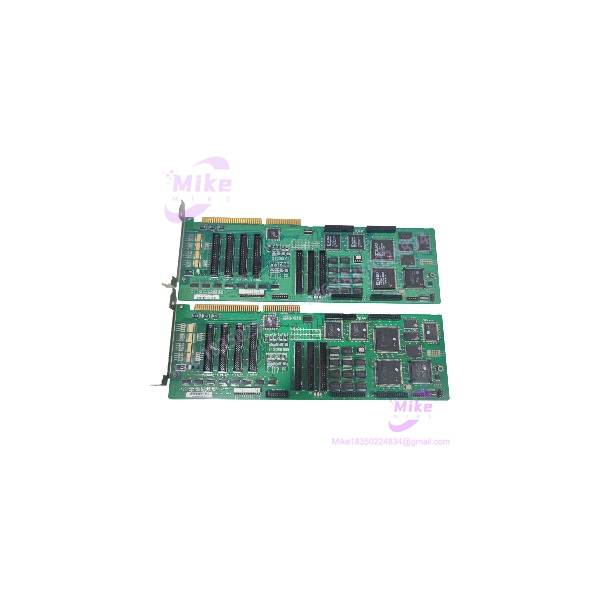
Rockwell MMC-BDPV81INA | 8-Axis ISA Motion Controller
Product Introduction
The Rockwell MMC-BDPV81INA is an eight-axis Full Size ISA motion-control board from the MMC motion-control family. It is designed for PC/AT or industrial-computer architectures and provides coordinated control for brush and brushless servo motors as well as stepper motors. The published MMC documentation specifically lists the BDPV81INA as an 8-axis Full Size ISA model.
This board is particularly relevant when maintaining an older machine whose original control computer still uses ISA hardware. The documented architecture provides 1–4 ms adjustable sampling, ±10 V 16-bit analog output, 3.75 MHz maximum pulse output, 7.5 MHz maximum position-feedback input, and 32 TTL-level user inputs plus 32 TTL-level user outputs.
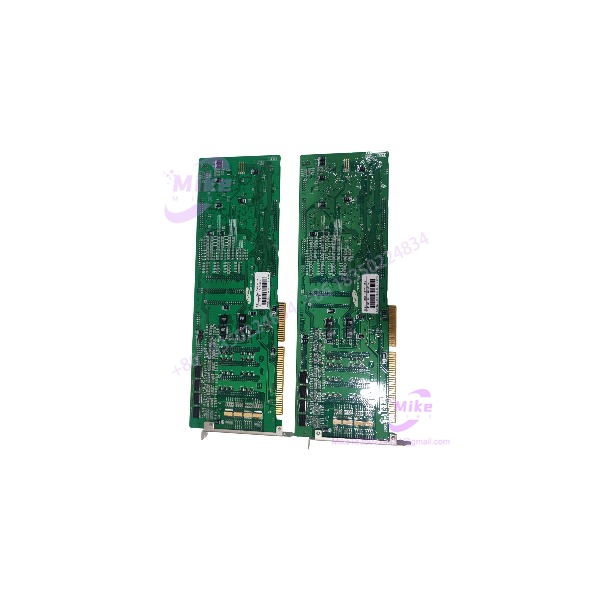
MMC-BDPV81INA
Key Technical Specifications
- Model: MMC-BDPV81INA
- Brand/Attribution: Rockwell / Samsung MMC
- Series: MMC Full Size ISA Series
- Board Type: Full Size ISA motion-control card
- Host Interface: PC/AT or industrial-computer ISA bus
- Controlled Axes: 8 axes
- Processor: TMS320C31 DSP
- Control Modes: Open-loop and closed-loop
- Motor Support: Brush servo, brushless servo, and stepper motors
- Sampling Rate: 1–4 ms adjustable
- Analog Output: ±10 V, 16-bit resolution
- Pulse Output: Up to 3.75 MHz, 50% duty cycle
- Pulse Frequency Resolution: 60 ns
- Position Command Range: 32-bit, ±2,147,483,647
- Acceleration/Deceleration Setting: 1–2,500 ms
- Position Feedback: Up to 7.5 MHz input frequency
- Feedback Filtering: Digital noise filtering
- Motion Profiles: Trapezoidal, asymmetric trapezoidal, S-curve, asymmetric S-curve
- Motion Functions: Point-to-point, linear interpolation, circular interpolation, spline interpolation, synchronized control
- System Inputs: Amplifier fault and in-position signals per axis
- System Outputs: Amplifier enable and amplifier fault reset per axis
- Limit Inputs: Positive, negative, and home
- User Inputs: 32 TTL-level points
- User Outputs: 32 TTL-level points
- Analog Input: 4 channels, 12-bit resolution, 32 µs conversion rate with MMC-AD11
- Control Power: +5 V approximately 2 A; +12 V approximately 0.5 A; −12 V approximately 0.5 A; −5 V approximately 0.3 A
- Operating Temperature: 0–50°C
- Relative Humidity: 20–95% RH, non-condensing
- Board Dimensions: Approximately 338 × 107 mm
- Hardware Status: Legacy / verify revision and condition
The published MMC specification gives the 3.75 MHz pulse and 7.5 MHz feedback values for the 8-axis PCI configuration, while the same catalog identifies MMC-BDPV81INA in the Full Size ISA family. The catalog’s model grouping and application configuration should therefore be used carefully when transcribing specifications to a specific board revision.
Application Scenarios & Pain Points
1. Legacy ISA Motion-Control Computers
The MMC-BDPV81INA is applicable to older industrial PCs where the motion-control architecture depends on a Full Size ISA expansion card.
Engineering pain point: A modern PCI or PCIe motion controller is not a bus-compatible replacement. Migrating the machine can require changes to the host computer, software, drivers, I/O wiring, and servo interface.
Procurement check: Confirm the target computer has a suitable ISA slot and that the original motion-control software can communicate with the replacement board.
2. Eight-Axis Servo Machinery
The 8-axis architecture allows multiple servo or stepper axes to be managed from one motion-control platform.
Engineering pain point: Matching axis count is only the first compatibility check. Servo command type, feedback hardware, enable logic, amplifier fault signals, limits, and position scaling must also match.
3. Multi-Axis Interpolation
The MMC architecture supports PTP, linear interpolation, circular interpolation, spline interpolation, and synchronized control.
Engineering pain point: Replacing the controller with independent-axis hardware may change trajectory generation, interpolation timing, and machine behavior.
4. Legacy ±10 V Servo Applications
The MMC specification provides ±10 V analog output at 16-bit resolution.
Engineering pain point: The ±10 V range does not establish compatibility with every amplifier. Verify command polarity, scaling, enable circuits, fault reset, and feedback configuration.
5. Obsolete Industrial Machine Repair
The MMC-BDPV81INA can serve as a spare or replacement candidate for legacy equipment that cannot economically be migrated to a modern control platform.
Engineering pain point: Board-level functionality does not guarantee system-level compatibility. The original host software, ISA configuration, motion parameters, firmware/revision, and external interface hardware must all be considered.
QA & Live Testing SOP
1. Identity Verification
- Photograph both sides of the PCB.
- Confirm the complete marking .
- Record PCB revision, serial number, date codes, labels, and option markings.
- Third-party listings identify Rev. 1.2, Rev. 1.4, and Rev. 1.5 examples, so the revision should be recorded rather than omitted.
- If a Rockwell, Samsung, OEM, or machine-builder identifier is present, record it separately.
2. PCB Inspection
- Inspect the ISA edge connector for oxidation, contamination, bent contacts, or wear.
- Check solder joints around connectors and mechanically stressed components.
- Inspect capacitors for leakage, swelling, or physical damage.
- Check for corrosion, burned components, previous repairs, or unauthorized modifications.
3. Controlled Power Test
- Handle the board using ESD-safe procedures.
- Install it in a compatible ISA test platform.
- Monitor startup current and supply behavior.
- Verify the required supply rails before connecting external motion hardware.
- Compare measured behavior with the documented control-power requirements.
4. Host Interface Test
- Confirm that the industrial PC initializes the motion-control board.
- Verify required ISA address, interrupt, and hardware configuration settings.
- Confirm the applicable legacy motion-control software and driver environment.
- Record the host computer, operating system, software version, and board revision used during testing.
5. Motion Interface Test
- Test analog output using appropriate measurement equipment.
- Verify command polarity and scaling.
- Test pulse output with an oscilloscope or suitable frequency counter.
- Verify position-feedback input using an appropriate signal simulator.
- Check amplifier-enable and amplifier-fault-reset functions.
6. Axis Test
- Start with a single axis.
- Confirm command direction and feedback direction.
- Verify position scaling and following behavior.
- Test amplifier enable and fault handling.
- Verify positive, negative, and home limit inputs.
- Progress to multiple-axis operation only after individual-axis testing passes.
7. User I/O Test
- Verify the 32 TTL-level inputs and 32 TTL-level outputs.
- Confirm signal voltage levels before connecting external devices.
- Do not connect 24 V industrial signals directly to TTL inputs.
- Test external I/O interface modules separately where applicable.
8. ESD Packaging
- Place the tested board in an ESD-safe bag.
- Protect the ISA connector from mechanical impact.
- Use rigid packaging to prevent PCB flex.
- Retain the board revision and test record with the unit.
Field Engineer’s Pitfall Guide
❗ Do not confuse with MMC-BDPV41INA. Both are Full Size ISA MMC models, but the is the 8-axis configuration while the BDPV41INA is the 4-axis configuration.
❗ Do not confuse the ISA version with PCI versions. The MMC catalog contains both Full Size ISA and PCI families. The host bus is a fundamental compatibility requirement.
❗ Verify the PCB revision. Third-party market reco boards marked Rev. 1.2, Rev. 1.4, and Rev. 1.5. Do not assume that all revisions are electrically or software-identical without documentation.
❗ Do not connect 24 V directly to TTL I/O. The documented user I/O is TTL level. Use the correct interface hardware for industrial field signals.
❗ Do not mix pulse-output and feedback specifications. Pulse output and encoder/position-feedback input are separate interfaces with separate frequency limits.
❗ Check the servo interface before powering an axis. Confirm ±10 V scaling, polarity, amplifier enable, fault reset, feedback direction, and limit logic before allowing machine movement.
❗ Do not assume a modern Ethernet protocol. The published MMC architecture describes an ISA/PC motion-control platform with dedicated motion I/O. Reseller descriptions that label this board as a generic process-control or Ethernet module should not override the primary MMC technical documentation.
Intent-Driven FAQ
What is the ?
The is an 8-axis Full Size ISA motion-control board associated with the MMC motion-control architecture.
an ISA or PCI card?
The MMC catalog identifies in the Full Size ISA series. It is intended for PC/AT or industrial-computer architectures using an ISA bus.
How many a support?
The specified configuration supports 8 axes, with open- and closed-loop control for brush/brushless servo motors and stepper motors.
What proces use?
The MMC specification identifies a TMS320C31 DSP processor.
What analog out provide?
The documented MMC architecture provides ±10 V analog output with 16-bit resolution.
What is the maximum pulse output frequency?
The published specification for the 8-axis configuration lists 3.75 MHz maximum pulse output with a 50% duty cycle.
What is the maximum position-feedback frequency?
The published 8-axis specification lists 7.5 MHz maximum position-feedback input, with digital noise filtering.
support interpolation?
Yes. The MMC architecture supports point-to-point, linear interpolation, circular interpolation, spline interpolation, and synchronized control.
provide user I/O?
Yes. The MMC specification lists 32 TTL-level inputs and 32 TTL-level outputs. Additional limit and axis-specific motion I/O are also provided through the MMC interface architecture.
What revi exist?
Third-party market records show examples identified as Rev. 1.2, Rev. 1.4, and Rev. 1.5. The revision printed on the actual PCB should be recorded for procurement and replacement matching.
an EtherNet/IP module?
The primary MMC documentation does not support that classification. It identifies the part within an ISA motion-controller architecture. Current reseller descriptions that classify it as a process-control or Ethernet module should be treated cautiously.
What should be verified before purchasing a replacement?
Verify the complete marking, PCB revision, ISA host computer, motion software, axis configuration, servo amplifier interface, feedback device, limit wiring, TTL I/O requirements, and machine-specific parameters.
Is the a drop-in replacement?
Do not assume drop-in compatibility solely from the model number or Rockwell attribution. For a legacy machine, the ISA host, software environment, board revision, motion parameters, servo interface, feedback system, and I/O configuration should all be matched.





