

Description
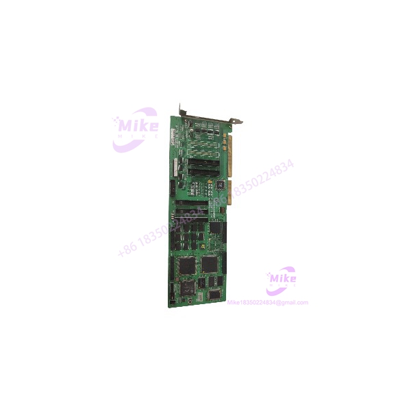
Rockwell MMC-BDPV41INA | 4-Axis ISA Motion Controller
Product Introduction
The Rockwell MMC-BDPV41INA is a four-axis industrial motion-control board from the MMC architecture, designed for installation in a Full Size ISA industrial PC or compatible PC/AT platform. The published MMC documentation identifies the BDPV41INA within the Full Size ISA family and specifies support for open- and closed-loop control of brush/brushless servo motors and stepper motors.
For legacy machine maintenance, this board is primarily valuable where the original ISA-based motion architecture, application software, and servo interface must remain in service. Its documented motion hardware provides 1–4 ms adjustable sampling, ±10 V 16-bit analog output, pulse output up to 1.5 MHz, position-feedback input up to 6 MHz, and 32 TTL-level inputs plus 32 TTL-level outputs.
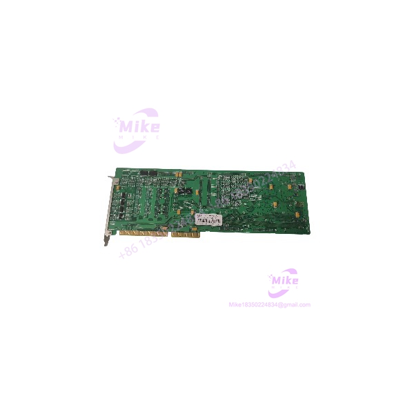
MMC-BDPV41INA
Key Technical Specifications
- Model: MMC-BDPV41INA
- Brand/Attribution: Rockwell / MMC
- Motion Controller Family: MMC Series
- Board Type: Full Size ISA motion-control card
- Host Interface: PC/AT or industrial-computer ISA bus
- Controlled Axes: 4
- Processor: TMS320C31 DSP
- Control Modes: Open-loop and closed-loop
- Motor Support: Brush servo, brushless servo, and stepper motors
- Sampling Rate: 1–4 ms adjustable
- Analog Output: ±10 V, 16-bit resolution
- Pulse Output: Up to 1.5 MHz, 50% duty cycle
- Position Command Range: 32-bit, ±2,147,483,647
- Position Feedback: Up to 6 MHz input frequency
- Feedback Filtering: Digital noise filtering
- Motion Profiles: Trapezoidal, asymmetric trapezoidal, S-curve, asymmetric S-curve
- Motion Functions: Point-to-point, linear interpolation, circular interpolation, spline interpolation, synchronized control
- System Inputs: Amplifier fault and in-position signals per axis
- System Outputs: Amplifier enable and amplifier fault reset per axis
- Limit Inputs: Positive, negative, and home per axis
- User Inputs: 32 TTL-level points
- User Outputs: 32 TTL-level points
- Optional Analog Input: 4 channels, 12-bit resolution, 32 µs conversion rate with MMC-AD11
- Control Power: +5 V/2 A, +12 V/0.5 A, −12 V/0.5 A, −5 V/0.3 A maximum specified consumption
- Operating Temperature: 0–50°C
- Relative Humidity: 20–95% RH, non-condensing
- Board Dimensions: Approximately 338 × 107 mm
- Hardware Status: Legacy / verify revision and condition
The MMC catalog explicitly groups MMC-BDPV41INA with the Full Size ISA 4-axis configuration and lists the same 338 × 107 mm physical size.
Application Scenarios & Pain Points
1. Legacy ISA Industrial PC Motion Systems
The MMC-BDPV41INA is suited to maintenance of older industrial computers that still provide a full-length ISA expansion architecture.
Pain point: A PCI or PCIe motion card cannot be assumed to replace an ISA controller without changing the host platform and potentially the motion software.
Procurement check: Confirm the target computer has the required ISA slot and that the original motion application can communicate with the replacement board.
2. Four-Axis Servo Machines
The controller supports four axes with open- and closed-loop operation and interfaces intended for servo and stepper applications.
Pain point: Axis count alone does not establish compatibility. The servo amplifier command interface, feedback device, limits, enable logic, and scaling must all match.
3. Coordinated Interpolation Equipment
The MMC architecture supports PTP, linear, circular, spline, and synchronized motion functions.
Pain point: Replacing this controller with a simple independent-axis pulse generator may alter trajectory generation and machine behavior.
4. Legacy ±10 V Servo Amplifier Systems
The specified ±10 V, 16-bit analog output makes the board applicable to legacy analog-command servo architectures.
Pain point: The ±10 V range does not prove that every servo amplifier is compatible. Command polarity, scaling, enable logic, fault reset, and feedback must be verified.
5. Obsolete Machine Spare Parts
The MMC-BDPV41INA is particularly relevant when an otherwise functional machine depends on discontinued ISA motion hardware.
Pain point: A replacement board may pass an electrical bench test but still fail system integration because of missing drivers, incompatible ISA resources, different firmware/revision behavior, or incorrect machine parameters.
QA & Live Testing SOP
1. Identity Verification
- Photograph the complete PCB before testing.
- Verify the physical marking .
- Record PCB revision, serial number, manufacturer markings, labels, and option markings.
- If the board carries an additional Rockwell, OEMax, Samsung, or machine-builder identifier, record it separately.
- Do not assign a different model solely from connector similarity.
2. PCB Inspection
- Inspect the ISA edge connector for oxidation, contamination, bent contacts, or mechanical wear.
- Check PCB traces and solder joints for damage.
- Inspect capacitors and exposed components for leakage, swelling, corrosion, or overheating.
- Look for evidence of previous repair or component replacement.
3. Controlled Power Test
- Use ESD-safe handling.
- Install the card in a compatible ISA test platform.
- Monitor supply current during startup.
- Compare measured consumption against the published control-power requirements.
- Investigate abnormal current draw before connecting external motion hardware.
4. Host Interface Test
- Confirm the industrial PC recognizes the installed motion controller.
- Verify required ISA hardware-resource settings.
- Confirm the applicable legacy driver and motion-control software environment.
- Record the operating system and software revision used during testing.
5. Motion Interface Test
- Verify ±10 V analog output with suitable measurement equipment.
- Check analog output polarity and scaling.
- Test pulse output with an appropriate frequency counter or oscilloscope.
- Verify position-feedback input using a compatible signal simulator.
- Check amplifier enable and amplifier fault-reset outputs.
6. Limit and User I/O Test
- Test positive, negative, and home limit inputs.
- Verify amplifier-fault and in-position inputs.
- Verify the TTL user I/O channels.
- Do not connect 24 V industrial signals directly to TTL inputs without the appropriate interface hardware.
7. Axis Commissioning Test
- Begin with one axis.
- Confirm command direction and feedback direction.
- Verify position scaling.
- Test amplifier enable and fault handling.
- Confirm limit behavior before allowing full travel.
- Progress to multi-axis interpolation only after individual-axis operation is confirmed.
8. ESD Packaging
- Place the board in an ESD-safe bag.
- Protect the ISA edge connector against mechanical damage.
- Use rigid packaging to prevent PCB flex.
- Keep documentation of the tested board revision with the unit.
Field Engineer’s Pitfall Guide
❗ Do not confuse with the PCI versions. The is documented in the Full Size ISA family. The MMC catalog separately identifies PCI configurations.
❗ Do not identify the board as an EtherNet/IP module. One reseller currently as a 24 VDC Ethernet/IP process I/O module, but those specifications conflict directly with the MMC motion-control documentation. The catalog identifies the board as an ISA motion controller with analog, pulse, feedback, limit, and TTL I/O functions.
❗ Verify the exact brand marking. Third-party inventories a with Rockwell and other MMC-family names. If the physical board is labeled Rockwell, retain Rockwell in the listing; otherwise document the actual PCB markings rather than assuming the manufacturer from a reseller page.
❗ Do not connect 24 V directly to TTL I/O. The documented user I/O is TTL level. Use the appropriate interface hardware when integrating industrial 24 V signals.
❗ Separate command and feedback specifications. The board’s 1.5 MHz pulse-output limit and 6 MHz feedback-input limit apply to different interfaces. Meeting one specification does not establish compatibility with the other.
❗ Check ISA resources and software. Even when the board is electrically functional, the original application may depend on specific ISA configuration, driver software, motion libraries, and machine parameters.
❗ Verify encoder polarity before servo enable. Incorrect feedback direction can produce an immediate position error or unintended motion. Perform feedback verification before allowing unrestricted axis movement.
Intent-Driven FAQ
What is the ?
The is a four-axis Full Size ISA motion-control board associated with the MMC motion-control architecture.
an ISA or PCI card?
It is documented as a Full Size ISA motion-control board. The MMC catalog lists it with the Full Size ISA family rather than the PCI family.
How many a support?
The documented configuration supports 4 axes with open- and closed-loop operation.
What proces use?
The MMC Full Size ISA specification identifies a TMS320C31 DSP processor.
What is the analog output specification?
The documented analog output is ±10 V with 16-bit resolution.
What is the maximum pulse output frequency?
The published maximum pulse output is 1.5 MHz with a 50% duty cycle.
What is the maximum position-feedback frequency?
The specified position-feedback input frequency is 6 MHz maximum, with digital noise filtering.
provide TTL I/O?
Yes. The documented configuration provides 32 TTL-level inputs and 32 TTL-level outputs.
support interpolation?
Yes. The MMC specification lists point-to-point, linear interpolation, circular interpolation, spline interpolation, and synchronized control.
an EtherNet/IP module?
The documented MMC technical specification does not support that identification. It describes an ISA motion-control board with dedicated motion, feedback, analog, pulse, limit, and TTL I/O functions.
What should be verified before buying a replacement?
Verify the complete marking, PCB revision, ISA host computer, motion software, servo amplifier interface, feedback device, limit wiring, TTL I/O requirements, and machine-specific configuration.
Is this a drop-in Rockwell replacement?
Do not assume drop-in compatibility from the Rockwell attribution alone. The host ISA architecture, software environment, motion parameters, servo interface, feedback system, and I/O wiring must match the original installation.





