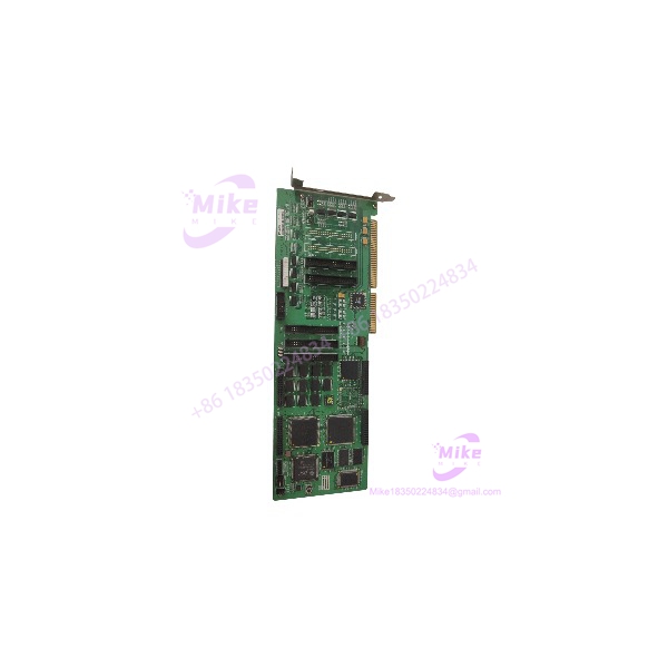
Description
Allen-Bradley 1746-NT8 | SLC 500 Analog Thermocouple Quantified Spec
Dynamic Product Introduction
Temperature monitoring drift and erratic process loops across legacy manufacturing lines frequently trace back to failing analog input modules. When an aging thermocouple card suffers from internal reference drift or damaged channel isolation due to electrical transients, temperature readings fluctuate wildly and cause unnecessary process shutdowns. The Allen-Bradley 1746-NT8 8-channel thermocouple module resolves these issues by delivering precise, multi-channel temperature conversion directly to the SLC 500 backplane.
Unlike standard voltage input cards, this specialized unit is engineered specifically to handle low-level millivolt signals while compensating for ambient temperature fluctuations at the terminal block. Maintaining absolute measurement accuracy on legacy SLC 500 heat-treating and processing systems demands exact hardware matching—making this thermocouple module essential for preventing costly thermal runaways or false alarms.
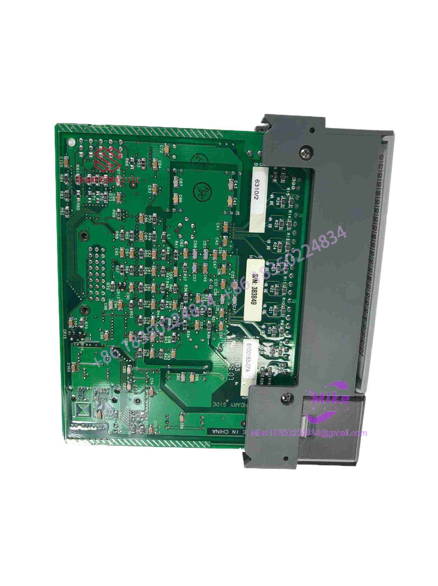
1746-NT8
Key Technical Specifications
| Parameter | Specification Detail |
| Manufacturer | Allen-Bradley (Rockwell Automation) |
| Catalog Number | 1746-NT8 |
| System Family | SLC 500 Modular I/O Platform |
| Module Type | 8-Channel Thermocouple / Millivolt Input Module |
| Supported Thermocouple Types | J, K, T, E, R, S, B, N |
| Millivolt Input Ranges | \pm 50 mV |
| Backplane Current Draw | 5 VDC: 100 mA; 24 VDC: 50 mA |
| Cold Junction Compensation | On-board automatic CJC sensors per terminal block |
| Operating Environment | Industrial control enclosures (0^\circ C to 60^\circ C) |
Global Sourcing & Live-Test SOP (Transparency Core)
Acquiring secondary-market legacy analog I/O hardware requires rigorous electrical and thermal validation to ensure zero calibration drift or channel cross-talk prior to installation. Our multi-stage qualification protocol covers:
- Inbound Verification: Incoming modules undergo high-magnification optical inspection along the terminal block connectors, backplane edge pins, and internal analog-to-digital converter traces to check for solder fatigue, dust accumulation, or thermal stress. OEM labels are authenticated against global traceability databases.
- Live Simulation: We slide the module into a dedicated Allen-Bradley SLC 500 test chassis rack powered by a live processor.
- Diagnostics: Engineers inject calibrated millivolt and thermocouple simulation signals across all eight channels simultaneously. Cold junction compensation accuracy and linearization curves are tested against standard NIST reference tables over an accelerated thermal soak cycle.
- Final Prep: Once testing criteria are met, the module is cleaned, contact fingers are treated for oxidation prevention, and the unit is packaged inside antistatic, shock-absorbing materials.
The Field Engineer’s Pitfall Guide
❗ Improper Shield Grounding: Never leave thermocouple signal cable shields floating or grounded at both ends. Always ground the shield at one end only (typically at the control panel ground bus) to prevent massive electromagnetic ground loops that will destroy temperature reading stability.
❗ Mixing Thermocouple Extension Wire Types: I’ve seen technicians splice standard copper wire into thermocouple runs instead of matching extension wire alloys, resulting in massive temperature measurement errors caused by secondary junction points.
❗ Hot-Plugging I/O Risks: Never insert or remove the 1746-NT8 module from the SLC 500 chassis while power is active. Doing so can cause electrical arcing, corrupt backplane data, and permanently damage the module’s internal circuitry.
Intent-Driven FAQ
Can the 1746-NT8 module accept standard 4-20mA or 0-10V analog signals?
No. This module is engineered strictly for low-level millivolt and thermocouple inputs. For standard analog process signals, use an input card like the 1746-NI4 or 1746-NI8.
Does each channel require its own isolated thermocouple probe?
While the module features differential inputs, proper grounding and wiring practices must be followed based on whether your thermocouple probes are grounded or ungrounded to prevent common-mode voltage interference.
What causes temperature readings to peg at maximum scale on a specific channel?
A max-scale (or up-scale) reading usually indicates an open circuit, such as a broken thermocouple wire, a loose terminal screw, or a burned-out junction element.
How do I configure the input types for the 1746-NT8?
Configuration is handled programmatically through programming software (such as RSLogix 500) by accessing the module’s configuration block to define the sensor type and filtering parameters for each individual channel.
What level of warranty is included with this surplus I/O module?
We back this component with a comprehensive one-year replacement warranty, covering material defects and analog measurement accuracy under normal industrial operating conditions.