Description
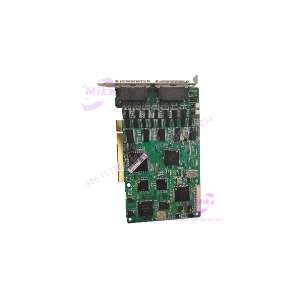
Allen-Bradley 1336-SN-SP10A | 1336 Inverter Interface Board Core Category
Dynamic Product Introduction
Communication breakdowns and erratic fault codes on legacy Allen-Bradley 1336 drives frequently point to a degraded interface or control board. When an internal logic or snubber interface board suffers from component fatigue under heavy thermal cycling, the inverter loses its ability to cleanly process operational commands, causing nuisance trips. The Allen-Bradley 1336-SN-SP10A interface board resolves these issues by restoring clean signal distribution and reliable backplane communication across the drive architecture.
Unlike generic circuit cards, this specialized Allen-Bradley PCBA is engineered to withstand the intense electromagnetic interference found inside heavy industrial motor control cabinets. Maintaining absolute operational stability on older 1336 drive platforms demands exact hardware matching—making this replacement board critical for eliminating unexpected downtime.
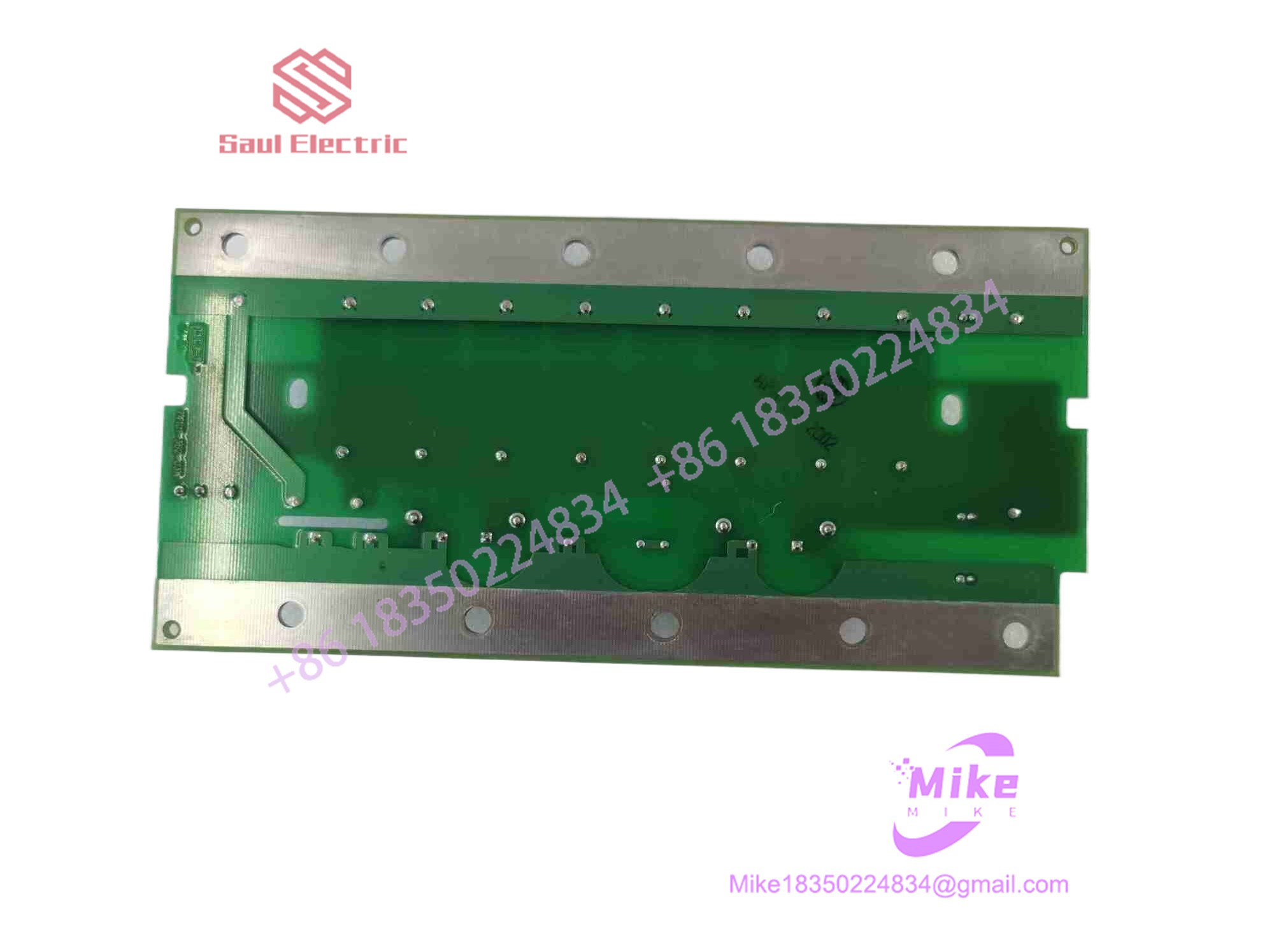
1336-SN-SP10A
Key Technical Specifications
| Parameter | Specification Detail |
| Manufacturer | Allen-Bradley (Rockwell Automation) |
| Catalog / Part Number | 1336-SN-SP10A (PCB ID: 7401-363-51) |
| Compatible Drive Series | Allen-Bradley 1336 / 1336 PLUS Adjustable Frequency Drives |
| Board Type | Inverter Interface / Snubber Control PCBA |
| Circuit Topology | Multi-layer surface-through-hole hybrid design |
| Interface Role | Internal logic routing and signal conditioning |
| Operating Environment | Industrial drive cabinet (0^\circ C to 50^\circ C) |
Global Sourcing & Live-Test SOP (Transparency Core)
Acquiring secondary-market legacy drive electronics requires rigorous electrical and optical verification to ensure zero component fatigue or logic corruption before installation. Our multi-stage qualification protocol covers:
- Inbound Verification: Incoming printed circuit boards undergo high-magnification optical inspection along the edge connectors, integrated circuits, and solder traces to check for micro-fissures, dust buildup, or thermal discoloration. OEM part and revision numbers are cross-referenced against historical archives.
- Live Simulation: We mount the interface board onto a dedicated Allen-Bradley 1336 test inverter chassis fixture configured to validate backplane communication traffic.
- Diagnostics: Engineers execute comprehensive signal-routing and logic-state tests using specialized diagnostic tools to verify data integrity across all communication channels under a simulated thermal load cycle.
- Final Prep: Once testing criteria are met, the PCBA is treated for moisture resistance where applicable, and sealed inside an antistatic, moisture-barrier shielding bag.
The Field Engineer’s Pitfall Guide
❗ DC Bus Capacitance Hazard: Never touch or replace internal drive circuit boards immediately after cutting power to the inverter. Always allow sufficient time for the massive DC bus capacitors to completely discharge to avoid lethal electrical shock.
❗ Mismatched Board Revisions: Installing an interface board with an incompatible hardware revision code into an older 1336 drive frame can cause communication handshaking failures and immediate fault lockouts upon power-up.
❗ Improper Ribbon Cable Seating: I’ve seen technicians rush a board replacement and fail to seat multi-pin internal ribbon harnesses securely, resulting in intermittent data drops and phantom drive error codes.
Intent-Driven FAQ
Can the 1336-SN-SP10A board be used across different horsepower ratings of the 1336 series?
Compatibility depends heavily on the specific drive sub-model and firmware architecture. Always verify that the exact catalog number and PCB layout match your existing hardware stack before installation.
What causes these interface boards to fail in industrial environments?
Prolonged exposure to elevated cabinet temperatures, airborne particulate buildup, and voltage transients from heavy motor switching are the primary drivers of component aging and failure.
How do I test if my drive communication error is caused by this interface board or the main processor?
Isolate the fault by checking diagnostic LED status indicators on the main control rack. If power rails are stable but internal data handshaking fails across the bus, the interface PCBA is likely compromised.
Are replacement components on this circuit board field-repairable?
Due to multi-layer trace architecture and sensitive surface-mount components, component-level field repairs are not recommended. Whole-board replacement ensures system safety and reliability.
What level of warranty is included with this surplus drive board?
We back this component with a comprehensive one-year replacement warranty, covering material defects and electrical performance under standard industrial operating conditions.