


Description
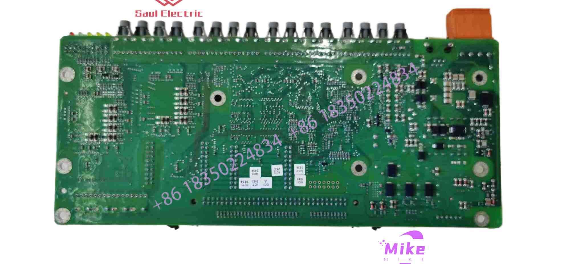
ABB PPC907BE Control Board 3BHE024577R0101
Digital control
By controlling analog circuits digitally, system cost and power consumption can be significantly reduced. Furthermore, many microcontrollers and DSPs already incorporate PWM controllers on -chip , making digital control implementation much easier.
In short, PWM is a method of digitally encoding analog signal levels. Using a high-resolution counter, the duty cycle of a square wave is modulated to encode the level of a specific analog signal. The PWM signal remains digital because at any given moment, the full-amplitude DC supply is either fully on or fully off. A voltage or current source is applied to the analog load as a repeating pulse sequence of on/off states. On means the DC supply is applied to the load, and off means the supply is disconnected. Any analog value can be encoded using PWM, provided the bandwidth is sufficient.
Most loads (whether inductive or capacitive ) require modulation frequencies higher than 10Hz. Imagine a light bulb switching on for 5 seconds, then off for 5 seconds, then on again, then off again… The duty cycle remains 50%, but the bulb will be lit for the first 5 seconds and off for the next 5 seconds. To achieve a 4.5V supply for the bulb, the on/off cycle must be sufficiently short compared to the load’s response time to the switching state change. To achieve the effect of a dimming light (but keeping it lit), the modulation frequency must be increased. The same requirement applies to other PWM applications. Typically, modulation frequencies range from 1kHz to 200kHz.
Hardware controller
Many microcontrollers include a built-in PWM controller. For example, Microchip ‘s PI C16C67 contains two PWM controllers, each with selectable on-time and period. The duty cycle is the ratio of the on-time to the period; the modulation frequency is the reciprocal of the period. Before performing PWM operations, such microprocessors require the following tasks to be completed in software:
Set the period of the on-chip timer /counter that provides the modulated square wave.
Set the on-time in the PWM control register.
This sets the direction of the PWM output; this output is a general-purpose I/O pin.
Start timer
Enable PWM controller
Although specific PWM controllers may differ in programming details, their basic ideas are usually the same.





