


Description
Woodward 9907-018 | 2301A Load Sharing and Speed Control Core Category
Dynamic Product Introduction
Balancing electrical loads across multi-generator utility ties requires a governor controller that can react to grid dynamics without hunting or thermal drift. The Woodward 9907-018 operates as a core 2301A system variant designed to govern diesel, gas, or steam prime movers while maintaining precise frequency stability. Unlike software-heavy programmable controllers that introduce execution lag, this hybrid unit uses reliable analog circuitry coupled with DIP-switch speed range selection for immediate, deterministic response loops.
Transitioning away from obsolete legacy iterations, this specific low-voltage configuration provides superior signal isolation and tighter active load-sharing capabilities across parallel bus architectures. Field history demonstrates that swapping in this unit eliminates erratic power surging during synchronizing phases while securing stable multi-unit operation under abrupt load steps.
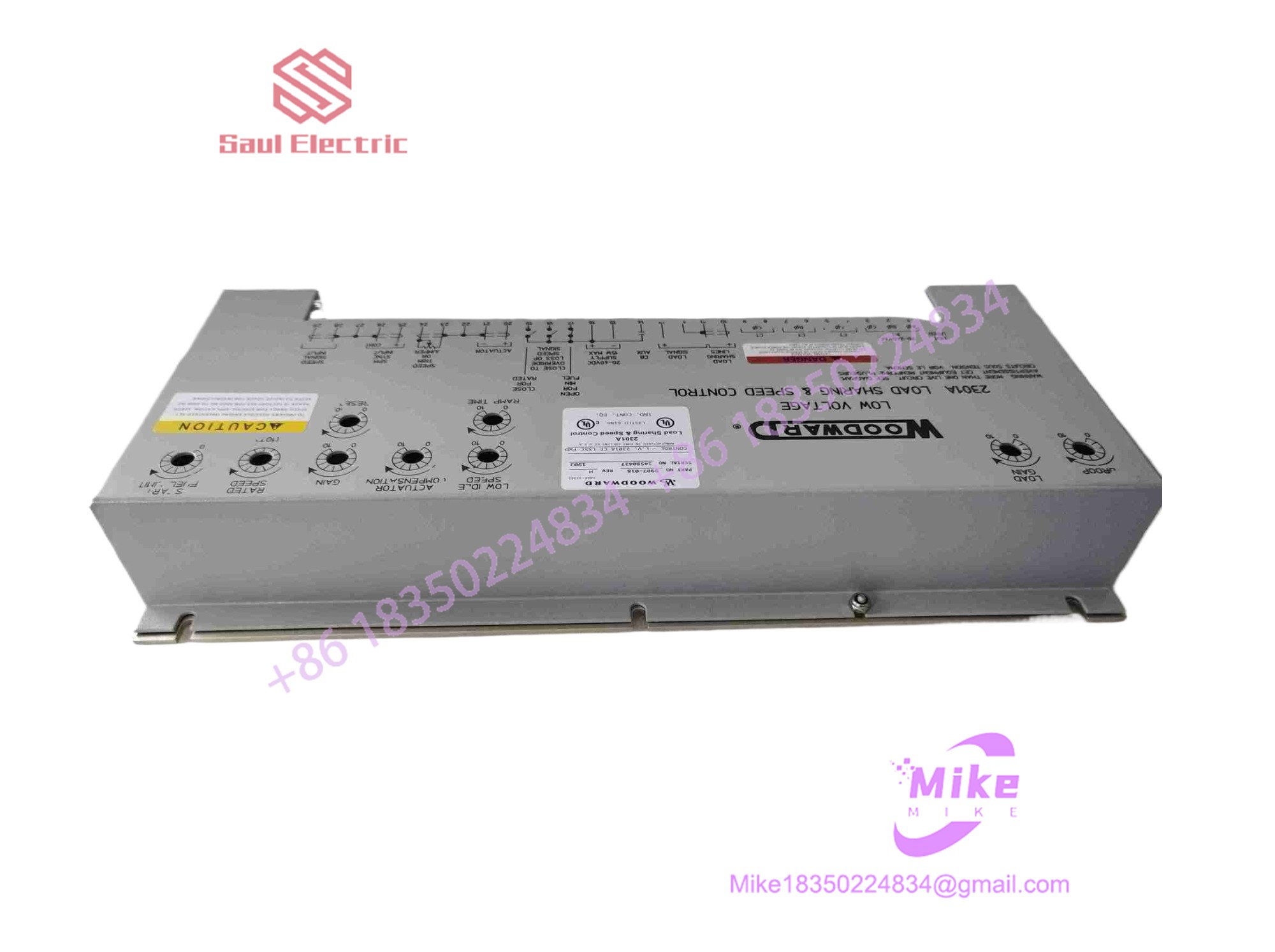
9907-018
Key Technical Specifications
- Supply Voltage: 20 to 32 VDC (Low-voltage DC architecture)
- Power Consumption: Approximately 12 watts nominal
- Speed Range Inputs: Selectable via internal DIP switches (500–1500 Hz, 1000–3000 Hz, 2000–6000 Hz, 4000–12000 Hz)
- Magnetic Pickup (MPU) Signal: 1 to 30 Vrms, 1000 ohms/kHz AC input impedance
- Actuator Output Current: 0 to 200 mA (30 to 45 ohms load resistance range)
- Speed Adjustment Range: External potentiometer trim (±5% adjustment)
- Start Fuel Ramp Time: Adjustable from 5 to 35 seconds
- Operating Temperature Range: -40°C to +85°C industrial ambient tolerance
- Vibration Resistance: 4 Gs (5 to 500 Hz frequency range)
- Dimensions & Weight: Standard 2301A compact chassis enclosure, ~1.5 kg (3.3 lbs) packed
Global Sourcing & Live-Test SOP (Transparency Core)
Deploying surplus or replacement control hardware on active generation assets demands stringent bench validation to eliminate early-failure risks.
- Inbound Verification: Incoming units undergo traceability audits against official manufacturing lot numbers, screening out unverified grey-market stock and inspecting terminal blocks for oxidation or mechanical wear.
- Live Simulation: Controllers are mounted on a specialized test rack powered by an isolated 24 VDC source, tied to an adjustable frequency signal generator simulating magnetic pickup (MPU) inputs.
- Diagnostics: Actuator outputs are swept across full 0–200 mA ranges using inductive dummy loads. Speed control loops, ramp times, and load-sharing line responses are measured via oscilloscope to verify PID stability under simulated load sharing.
- Final Prep: Once calibration logs verify zero drift, internal configuration settings are documented, and the hardware is packaged in an anti-static moisture-barrier bag.
The Field Engineer’s Pitfall Guide
❗ Mismatched MPU Frequency Switch Settings: Forgetting to adjust the internal DIP switches to match your specific flywheel gear teeth frequency range causes the unit to miscalculate engine speed, immediately driving the actuator to maximum fuel or zero position on startup. (I’ve seen plants blow smoke on initial crank simply because a technician left the switches configured for a high-speed turbine instead of a slow diesel.) Always cross-reference gear teeth counts before applying power.
❗ Unbalanced Load-Sharing Line Impedance: Tying the load-sharing interconnect lines (typically terminals inter-connecting parallel units) using unshielded or incorrectly terminated wire introduces circulating ground currents, causing generators to fight each other for kW load dominance. Always use shielded twisted-pair cabling grounded strictly at one end.
❗ Ignoring Auxiliary Power Ripple: Supplying this controller from an unconditioned battery charger bus carrying high AC ripple voltages will destabilize the internal reference circuits. Always verify DC bus cleanliness using a True-RMS meter prior to landing power lines.
Intent-Driven FAQ
Will swapping this control unit cause me to lose my custom engine calibration?
No. The 9907-018 relies on physical analog potentiometers (for GAIN, RESET, and DROOP) and hardware DIP switches rather than software-stored memory. You must manually record your potentiometer turn settings prior to removal so you can mirror them exactly on the replacement module.
Can this controller be hot-swapped while the generator is running in parallel?
No. Hot-swapping a speed and load controller on an active, synchronised prime mover will instantly sever governor control, risking severe engine overspeed or an immediate reverse-power plant trip. Always take the unit offline, drop load, and de-energize the 20–32 VDC supply before touching wiring.
What causes the unit to enter an unmanaged minimum fuel state upon start?
A sudden drop to minimum fuel usually indicates a lost or degraded MPU signal, an incorrect frequency range switch setting, or an open circuit in the actuator coil loop. Check AC voltage directly at the MPU terminals during cranking to confirm proper sensor air-gap clearance.
Is the 9907-018 compatible with digital PLC SCADA systems?
The 9907-018 is fundamentally an analog-hybrid controller designed for standalone or hardwired analog supervision (4–20 mA remote speed setpoints). It does not feature native Ethernet or Modbus protocol stacks unless paired with external protocol converter gateways.
What kind of warranty covers surplus 9907-018 units?
Reputable industrial suppliers typically back tested surplus or refurbished automation components with a standard 1-to-2 year replacement warranty, backed by an independent bench test report confirming actuator output linearity and MPU frequency response.





