


Description
Woodward 8406-113 | EGCP-3 LS Generator Control
Product Introduction
When several generator sets must operate in parallel, the difficult part is not simply starting each engine. Frequency, voltage, kW, reactive power, breaker status, sequencing, and load-sharing logic all have to stay coordinated. The Woodward 8406-113 is the EGCP-3 LS (Load Sharing) Engine Generator Control Package, built specifically for that environment. It combines engine-generator management with synchronization and load-sharing functions rather than leaving those jobs to a collection of unrelated controllers.
The electrical specifications are equally important. The 8406-113 operates from 18–32 VDC, accepts generator PT inputs from 27–300 VAC, and provides 0–5 A AC RMS nominal CT inputs. Generator frequency is monitored across 40–70 Hz, while magnetic-pickup input supports 100–24,950 Hz. Speed bias can be configured for ±3 VDC, 0.5–4.5 VDC, 5 V peak 500 Hz PWM, or 4–20 mA, giving the controller considerable flexibility when interfacing with different governor systems.
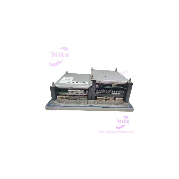
8406-113
Key Technical Specifications
- Manufacturer: Woodward
- Part Number: 8406-113
- Control Family: EGCP-3
- Model Type: LS — Load Sharing
- Primary Application: Diesel and gas engine generator control
- Supply Voltage: 18–32 VDC
- Nominal Supply: 24 VDC
- Power Consumption: ≤20 W nominal; 22 W maximum
- PT Inputs: 27–300 VAC
- CT Inputs: 0–5 A AC RMS nominal; 7 A AC RMS maximum
- Short-Time CT Rating: 10 × rated current for 1 second
- Generator Frequency: 40–70 Hz
- Magnetic Pickup: 100–24,950 Hz
- Discrete Inputs: 16
- Analog Inputs: 4–20 mA and 1–5 VDC
- Analog Outputs: 4–20 mA
- Speed Bias: ±3 VDC, 0.5–4.5 VDC, 5 V peak 500 Hz PWM, or 4–20 mA
- Voltage Bias: ±1 VDC, ±3 VDC, ±9 VDC, or 4–20 mA
- Discrete Outputs: 12 low-side drivers, 200 mA
- Serial Ports: 3
- Communication Interfaces: RS-485, RS-422, RS-232
- Operating Temperature: -20 to +70°C
- Storage Temperature: -40 to +85°C
- Humidity: 95% at +20 to +55°C
- Mechanical Protection: IP54 when properly installed in an appropriate enclosure
- Approximate Dimensions: 358 × 282 × 135 mm
- Approximate Weight: 4.3 kg
- Interface: Dual backlit LCD display with keypad
- Application Class: EGCP-3 LS load-sharing generator control
Woodward’s own EGCP-3 manual identifies 8406-113 specifically as the EGCP-3 Engine Generator Control Package, LS Model, while 8406-114 is the separate MC model. That distinction matters when replacing a controller in a multi-generator installation.
Application Scenarios & Pain Points
Multi-Generator Load Sharing
Without coordinated load sharing: One generator can carry disproportionate kW while another sits underloaded. That creates unnecessary mechanical stress, inefficient fuel use, and unstable plant operation.
With the 8406-113: The LS controller is intended to operate with other generator controls and coordinate load-sharing functions across a parallel generation system. Woodward’s current replacement database identifies 8406-113 as “LS” and maps it toward the easYgen-3500XT-P2 replacement platform.
Synchronization Before Breaker Closure
A generator cannot simply close onto a live bus because its engine reached rated RPM.
The control system must evaluate generator voltage, frequency, phase relationship, breaker feedback, and synchronization conditions. The 8406-113 provides generator sensing and dedicated speed/voltage bias outputs for this control chain. Its generator frequency measurement range is 40–70 Hz.
Peak-Shaving and Parallel Operation
In a facility where generator capacity is brought online as plant demand increases, the controller has to coordinate engine start/stop sequencing and generator loading.
That is where an LS controller earns its place. It is designed as part of a generator-control network rather than as a simple start/stop relay.
Legacy Power Plant Maintenance
The uncomfortable reality: this is now legacy hardware.
Woodward’s own replacement database lists 8406-113 as an LS product and points users toward the easYgen-3500XT-P2 as its replacement, with an explicit warning that LON is not supported in the replacement.
For maintenance teams, that makes an exact 8406-113 particularly useful when an installed system still depends on the original architecture and a full controls migration is not immediately practical.
Single-Phase Zig-Zag Applications
There is an especially important revision issue here.
Woodward released application software 5418-144G.SCP for existing 8406-113 B through F controls, upgrading them to 8406-113 G for applications using the newly supported single-phase Zig-Zag generator configuration. If the installed generator uses this configuration, the software revision needs to be checked before assuming two LS units are functionally identical.
QA & Live Testing SOP
For generator-control equipment, a display that powers up does not equal a tested controller.
- Part-number verification: Confirm the nameplate reads Woodward 8406-113.
- Model verification: Confirm it is the version—not 8406-114 MC.
- Revision inspection: Record hardware revision and application software revision.
- Power test: Apply controlled 24 VDC nominal power within the specified 18–32 VDC range and verify startup behavior.
- Display/keypad test: Check both LCD displays, keypad response, menus, alarms, and configuration access.
- PT input test: Apply a controlled AC test signal within the appropriate range and verify voltage sensing.
- CT input test: Inject a controlled current signal and verify measurement response.
- Frequency test: Verify generator-frequency sensing across the applicable 40–70 Hz range.
- Speed-bias test: Measure the configured output using a calibrated meter or oscilloscope.
- Voltage-bias test: Verify the selected output range and response.
- Discrete I/O: Check input recognition and output-driver operation using an approved bench procedure.
- Communications: Verify the applicable RS-485, RS-422, and RS-232 interfaces.
- Configuration preservation: If replacing an installed unit, document the existing parameters before disturbing the system.
- ESD packaging: Protect the controller, connectors, display, and circuit assemblies against static discharge and impact during shipment.
For an actual generator installation, bench testing should never be treated as proof that the controller is ready for immediate synchronization. Final commissioning requires site-specific verification of PT ratios, CT ratios, governor interface, AVR interface, breaker logic, protection settings, and load-sharing configuration.
Field Engineer’s Pitfall Guide
❗ Do not confuse 8406-113 with 8406-114. Both belong to the family, but 8406-113 is the LS Load Sharing model, while 8406-114 is the MC model. Woodward’s documentation explicitly separates the two.
❗ Check the software revision. Woodward documents 8406-113 B, C, D, E, and F upgrades to 8406-113 G for a specific single-phase Zig-Zag generator application. If your site uses that configuration, revision compatibility is not a minor detail.
❗ Do not assume an easYgen replacement is electrically or functionally identical. Woodward’s own replacement database maps 8406-113 to the easYgen-3500XT-P2, but specifically notes that LON is not supported in the replacement. A migration therefore requires an architecture review, not simply a part-number substitution.
❗ Verify the PT range before energizing the sensing circuit. The 8406-113 accepts 27–300 VAC PT inputs. The programmed PT ratio and actual generator voltage must agree with the installation documentation.
❗ Do not test synchronization by trial and error on a live bus. A wrong phase relationship or incorrect PT scaling can turn a commissioning mistake into a serious mechanical and electrical event.





