


Description
Vibro-Meter 200-510-071-113 200-510-111-034 | VM600 MPC4 Machinery Protection Card
Dynamic Product Introduction
Field engineers know the frustration of chasing false vibration spikes caused by bad signal conditioning rather than real mechanical wear. Relying on centralized PLC logic to process raw proximity or acceleration waveforms introduces network latency that can cost you a turbine runner if a blade breaks. Inserting the 200-510-071-113 MPC4 front processing card alongside its matching 200-510-111-034 IOC4 rear terminal module fixes this by executing high-speed digital signal processing directly at the rack slot level.
This specific card pair handles four continuous dynamic channels alongside two phase reference or speed inputs. By processing signal filters and executing trip comparisons in hardware, the 200-510-071-113 bypasses main controller overhead to trip protective relays in under 10 milliseconds. Combined with a dynamic range exceeding 100 dB across its 24-bit delta-sigma converters, this module set guarantees clean, uncorrupted orbit, overall amplitude, and order-tracking data for demanding critical asset loops.
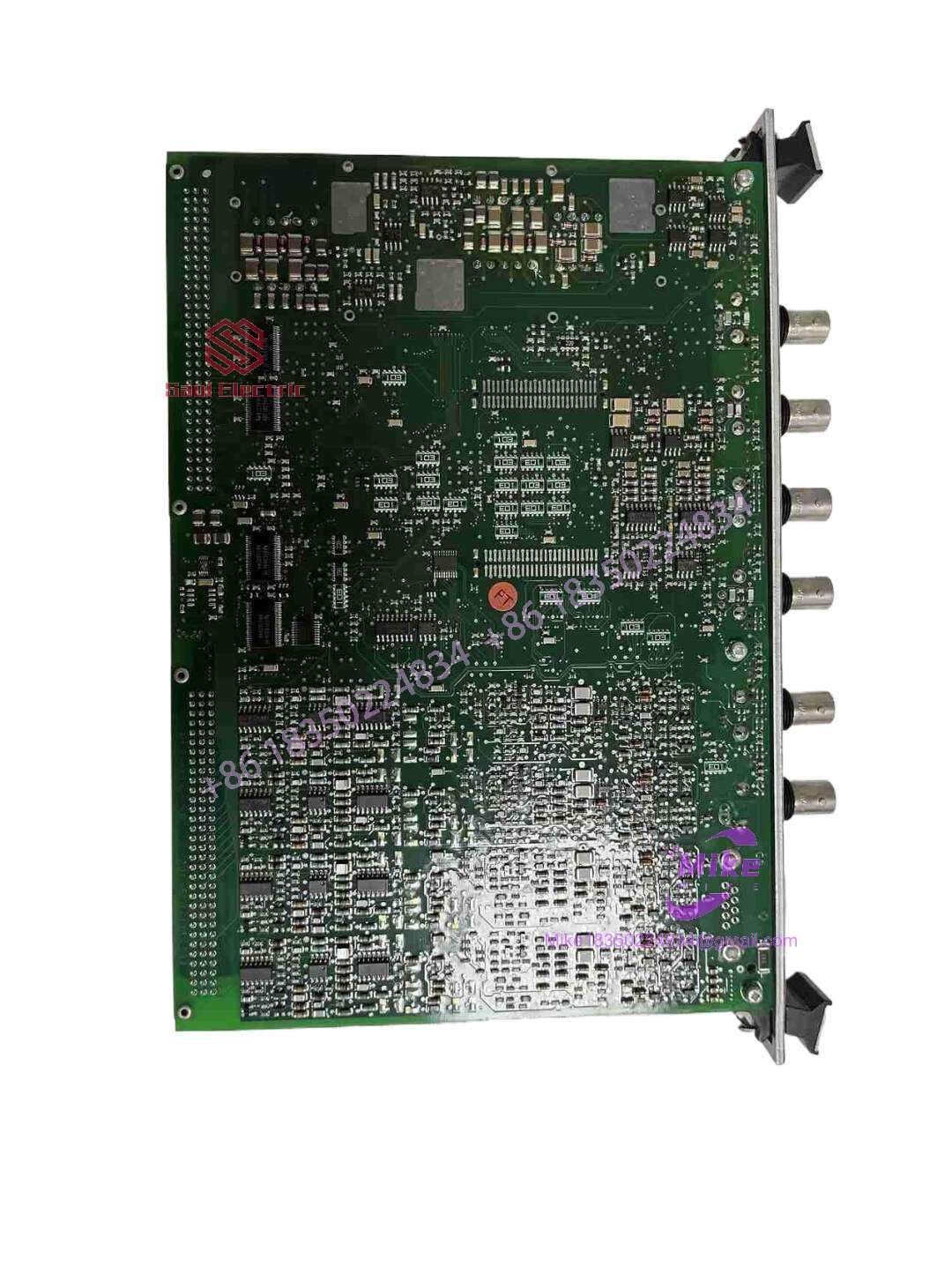
200-510-071-113 200-510-111-034 VM600 MPC4
Key Technical Specifications
| Parameter | Specification (200-510-071-113 Front / 200-510-111-034 Rear) |
| Dynamic Inputs | 4 channels (Accepts voltage \pm 20 V, current 2 to 20 mA, or IEPE/Piezoelectric sensors) |
| Speed/Auxiliary Inputs | 2 channels (Proximity probes, magnetic pickups, or optical sensors up to 50 kHz) |
| A/D Conversion | 24-bit resolution Delta-Sigma ADC per channel |
| Frequency Response | DC to 20 kHz (Software-configurable high-pass and low-pass tracking filters) |
| Signal Out | 4 raw buffered outputs (front panel BNCs / rear terminal) + 4 scalable 4–20 mA DC outputs |
| Onboard Relays | 3 programmable mechanical relays on the IOC4 card (OK, Alert, Danger) |
| Rack Interface | Standard VM600 backplane (VMEbus architecture) |
| Power Consumption | < 12 W typical from VM600 backplane |
| Processing Speed | Hardware trip execution delay < 10 ms |
| Operating Temp Range | -20^\circC to +65^\circC (-4^\circF to 149^\circF) |
Global Sourcing & Live-Test SOP
 ┌──────────────────────┐      ┌──────────────────────┐      ┌──────────────────────┐
   │ 1. INBOUND AUDIT     │ ───► │ 2. BENCH TEST & RIG  │ ───► │ 3. DIAGNOSTICS & RUN │
   │ • Serial Verification│      │ • VM600 Rack Mount   │      │ • Signal Generator   │
   │ • Visual Hardware QC │      │ • IOC4 Keying Align  │      │ • Modbus Verification│
   │ • OEM Seal Integrity │      │ • Backplane Lineup   │      │ • 24-Hr Thermal Load │
   └──────────────────────┘      └──────────────────────┘      └──────────────────────┘
Inbound Audit & Traceability
Each incoming 200-510-071-113 and 200-510-111-034 unit undergoes strict hardware validation before entering our ready-to-ship inventory. We verify Meggitt/Vibro-Meter manufacture markings, inspect edge connector pins for micro-fractures or gold plate erosion, and audit PCB trace layers for unauthorized component repairs.
Live Bench Simulation
We never test these modules on open benches with clip leads. The 200-510-071-113 front card is installed in a live VM600 chassis powered by an RPS600 unit, mated directly to the 200-510-111-034 IOC4 card through the rear backplane interface to mirror real cabinet operation.
Diagnostics & Signal Verification
Using precision function generators and Fluke diagnostic equipment, we validate every input and output path:
- Dynamic Voltage & Current Sweep: Inject simulated AC/DC signals from -20 V to +20 V across all four dynamic channels to verify ADC linearity and amplitude accuracy.
- Trip Relay Actuation Test: Force alert and danger limit breaches to confirm that IOC4 output relays physically change state within the specified sub-10ms window.
- Thermal Stress Burn-In: Run the board assembly inside a temperature-controlled chamber at 50^\circC under full continuous load for 24 hours to eliminate potential thermal drift or DSP memory errors.
- Firmware Logging: Read and record onboard flash memory levels and pack the cards in anti-static ESD shielding prior to storage.
The Field Engineer’s Pitfall Guide
❗ Pitfall 1: Overlooking Rear IOC4 Sub-Model Compatibility
Never assume any MPC4 front module pairs with any rear card. Installing a 200-510-071-113 front processing card with a mismatched variant (e.g., swapping a
-034with an open-collector-011version) can lead to unacknowledged backplane bus faults or non-functioning trip relays. Honestly, I’ve seen plant technicians waste two shifts troubleshooting a “dead” channel simply because they matched the front board but ignored the specific trailing dash numbers on the rear connector board.
❗ Pitfall 2: Live Hot-Swapping Without Output Logic Isolation
While the VM600 backplane supports live card insertion, pulling a live 200-510-071-113 card without first bypassing the associated emergency shutdown (ESD) logic will trip downstream safety relays. Always place the channel or rack protection loops into “Bypass” or “Maintenance Mode” via software before disengaging retaining screws.
❗ Pitfall 3: Transducer Power Jumper & Grounding Mistakes
Failing to verify input hardware jumpers or software settings before swapping from a passive eddy-current probe (which needs a -24 VDC supply from the ) to a self-powered IEPE accelerometer will damage the front-end input stage. Furthermore, ensure cable shielding connects exclusively at the terminal block—grounding the shield at both the sensor head and the rack creates ground loops that introduce 60 Hz noise and trigger false alarms.
Intent-Driven FAQ
Will I lose channel configurations when swapping in a replacement 200-510-071-113 card?
Yes, if you do not restore the project file. The 200-510-071-113 stores channel scale factors, filtering frequencies, and relay logic thresholds in onboard non-volatile memory. After inserting a replacement card, you must connect via the Vibro-Meter MPS Configurator software to upload or push the saved .mps project parameter set to the new module.
What is the exact purpose of the 200-510-111-034 rear card?
The 200-510-071-113 front card houses the digital signal processor (DSP) and main CPU, but it lacks field wiring terminals. The 200-510-111-034 rear card resides in the matching rear slot of the rack to provide physical screw terminal blocks for field sensor wiring, raw buffered signal outputs, 4–20 mA DC proportional outputs, and hardwired relay contacts.
How do I resolve a firmware mismatch between the new MPC4 card and the rack?
Connect to the rack through the CPUM controller card using the MPS Configurator tool. Query the hardware inventory tab to check the firmware version on slot 200-510-071-113. If the replacement card runs a higher or lower firmware version than the rest of the rack, use the flash utility within the software suite to match the firmware across all installed MPC4 modules.
Can this card pair operate independently if the rack CPUM controller fails?
Yes. Machinery protection logic is executed locally on the 200-510-071-113 card itself. Even if the main rack system controller (CPUM) or communications bus suffers a complete hardware failure, the MPC4 card continues to process sensor inputs and actuate the mechanical relays on the 200-510-111-034 card without interruption.
What warranty covers these surplus or refurbished Vibro-Meter modules?
All 200-510-071-113 and 200-510-111-034 module sets sourced through our inventory include factory seals or full reconditioning reports. Every unit is backed by a comprehensive 1-year replacement warranty covering all signal conditioning channels, backplane communications, and physical relay outputs.





