


Description
Terasaki ERB-112 | Marine Control Circuit Board
Product Introduction
In a marine control cabinet, the PCB is rarely an isolated component. Its connector assignments, revision level, and relationship to the surrounding controller determine whether a replacement actually belongs in the system. Terasaki ERB-112 is identified in multiple current industrial listings as a Terasaki control/circuit-board assembly, with associated K/751/3-002 variants appearing across the secondary market.
That makes ERB-112 primarily a lifecycle-maintenance component for installed Terasaki equipment. Several variants are encountered in the field — including K/751/3-002A and K/751/3-002B — so purchasing by the base ERB-112 designation alone is not sufficient when a plant requires an exact like-for-like replacement.
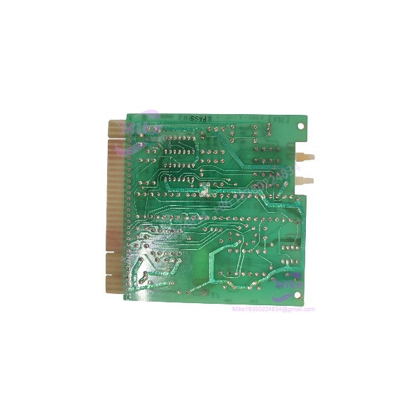
ERB-112
Key Technical Specifications
- Manufacturer: Terasaki
- Model: ERB-112
- Product Type: PCB / electronic control-board assembly
- Application Class: Marine and industrial automation
- Known Associated Part Number: K/751/3-002
- Documented Variant: K/751/3-002A
- Documented Variant: K/751/3-002B
- Additional Variant Found: K/751/3-002E
- Board Function: Control-system electronic circuitry; exact functional assignment depends on board revision and host equipment
- Installation: System-specific PCB replacement
- Communication Interface: Not safely established from the base ERB-112 designation
- Supply Voltage: Not safely established from the available documentation
- I/O Specification: Not safely established as a universal specification
- Environmental Rating: Verify against the original Terasaki system documentation
Current listings explicitly identify as a PCB/control-board product, while individual variants carry different suffixes and references. One listing, for example, identifies K/751/3-002B, while another identifies K/751/3-002E as a generator exhaust gas/thermocouple outlet card. This is exactly why the complete board marking matters.
Application Scenarios & Pain Points
Marine automation maintenance
Terasaki equipment installed aboard vessels can remain in service for many years after the original electronics have become difficult to source. can therefore be relevant when maintaining an existing controller rather than redesigning the cabinet.
Legacy control-board replacement
A failed PCB does not necessarily justify replacement of an entire control assembly. A correctly identified variant can provide a more direct maintenance path when the remaining system hardware is serviceable.
Generator control systems
Some variants are specifically associated in current listings with generator exhaust-gas and thermocouple outlet circuitry. The suffix must therefore be matched to the installed application before procurement.
Spare-parts inventory
For an aging marine automation system, keeping the exact PCB reference in stock can shorten troubleshooting during an unplanned outage. The inventory record should include the complete K/751/3-002 suffix rather than only .
Refit and overhaul work
During a vessel overhaul, technicians may encounter boards that are no longer supported through normal distribution channels. A tested legacy PCB can be useful when maintaining the original architecture is preferable to a control-system retrofit.
QA & Live Testing SOP
We treat as a revision-sensitive electronic assembly.
Step 1 — Identity verification
We record the Terasaki model marking, complete K/751/3-002 reference, suffix letter, revision information, connector configuration, and any additional board identifiers.
Step 2 — Physical inspection
The PCB is checked for corrosion, damaged terminals, cracked solder joints, burned components, contamination, lifted traces, and mechanical damage. Marine equipment deserves particular attention here because long-term exposure can affect connectors and PCB surfaces.
Step 3 — Component-level screening
Before energization, we inspect visible protection components and check for obvious shorts across the applicable power paths. We do not apply an assumed supply voltage merely because another listing specifies one.
Step 4 — Functional verification
Where the correct Terasaki host equipment or approved test fixture is available, the board is powered and checked for expected control behavior, signal response, and system-level feedback.
Step 5 — Documentation
The tested board is labeled with its exact hardware identification and test status. ESD protection is used for storage and shipment.
Field Engineer’s Pitfall Guide
❗ Do not order by alone when the application is safety- or control-critical. Current records show multiple K/751/3-002 suffixes associated with . The suffix can identify a materially different board configuration.
❗ Do not assume every is a generic PLC processor. One current listing categorizes a K/751/3-002 [122] unit as a PLC processor module, while other listings identify simply as a PCB/control board. The classification is inconsistent enough that the physical board and host-system documentation should take priority.
❗ Do not apply an unverified power supply. No reliable manufacturer-level documentation located for the base establishes a universal input voltage, current consumption, or I/O map. Treat those values as application-specific until verified.
Intent-Driven FAQ
Q: What is Terasaki ?
A: is identified in current industrial-spares records as a Terasaki electronic PCB/control-board assembly used in marine and industrial equipment.
Q: What is the K/751/3-002 reference?
A: It is an associated Terasaki board reference appearing with . Current records show A, B, and E suffix variants, so the complete designation should be matched before installation.
Q: Is K/751/3-002A interchangeable with K/751/3-002B?
A: Do not assume interchangeability. The existence of different suffixes indicates configuration or revision differences may exist. Verify the installed system and complete board marking first.
Q: Is a PLC processor?
A: Some secondary listings categorize particular assemblies that way, but the broader evidence identifies the product as a PCB/control-board assembly. The exact functional role should be determined from the complete board reference and host equipment.
Q: What voltage does require?
A: A universal supply voltage should not be assumed from the base model number. Verify the exact PCB revision and Terasaki equipment documentation before applying power.
Q: Can be used for marine generator equipment?
A: Yes, variants appear in marine generator-related control applications, including a documented K/751/3-002E board described as a generator exhaust-gas/thermocouple outlet card. The exact suffix is therefore critical.
Q: What should I provide when requesting an replacement?
A: Provide the complete marking, the K/751/3-002 suffix, revision number if present, connector-side photos, and the Terasaki equipment model. That information greatly reduces the risk of receiving the wrong board variant.





