


Description
SMC EX120-SPR1-B PROFIBUS-DP SI Unit 16 Outputs
Product Introduction
A pneumatic manifold becomes difficult to integrate when every solenoid requires separate PLC wiring. The SMC EX120-SPR1-B solves that wiring problem at the fieldbus level by acting as the PROFIBUS-DP slave interface between a PLC and an SMC solenoid-valve manifold.
The EX120-SPR1-B is an SMC EX120-series Serial Interface (SI) unit specifically designed for PROFIBUS-DP. SMC’s documentation states that the unit controls SMC solenoid valves through PROFIBUS-DP and provides a maximum of 16 output drivers. The EX120 housing configuration is intended for direct mounting without a ribbon cable and is associated with compatible VQ and SV valve configurations.
This distinction matters during procurement. The EX120-SPR1-B is the electronic fieldbus interface, while the pneumatic valve manifold and individual solenoid valves are separate system components. SMC documentation identifies the EX120-SPR1-B as supporting VQ1000/2000 valve configurations and specifies the appropriate manifold/sub-base ordering families.
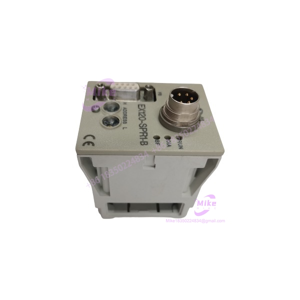
EX120-SPR1-B
Key Technical Specifications
- Exact model: EX120-SPR1-B
- Manufacturer: SMC Corporation
- Series: /121/122 Serial Transmission System
- Interface type: PROFIBUS-DP SI unit
- Network role: PROFIBUS-DP Slave
- Physical bus: RS-485
- Bus connector: 9-pin D-Sub
- Power connector: 5-pin round connector conforming to DIN 45322
- Communication protocol: PROFIBUS-DP
- Applicable standard: IEC 61158 / EN 50170
- Maximum bus transmission rate: 12 Mbit/s
- Minimum bus transmission rate: 9.6 kbit/s
- Baud-rate selection: Automatic detection from PROFIBUS-DP master
- Maximum participants without repeater: 32 total participants
- Maximum repeaters: 3
- Maximum participants with three repeaters: 126 slaves
- Supply voltage: +24 VDC ±10%
- Allowable supply range: 21.6–26.4 VDC
- Electronics current: 70 mA maximum at rated voltage, without load
- Valve load current: 1.4 A maximum
- Output channels: 16
- Output voltage: +24 VDC ±10%
- Output polarity: Minus common
- Maximum output power per output: 2.1 W
- Output protection: One micro-fuse per byte / two-byte output group
- Minimum slave interval: 0.1 ms
- Enclosure protection: IP20
- Operating temperature: 0 to +50°C
- Storage temperature: -20 to +85°C
- Relative humidity: 10–95%, non-condensing
- Communication diagnostics: BF and DIA LEDs
- Supply/status indication: RUN LED
- Addressing: Hardware rotary-switch addressing or software addressing
- Hardware address range: 02–99
- Software address range: 02–126
- Configuration file: GSD
- Hardware-address GSD: SMCB1401.GSD
- Software-address GSD: SMCB1400.GSD
- Valve connection: Internal valve-manifold wiring through the SI interface
- Maximum solenoid coils: 16
- Compatible valve families documented for : SMC VQ1000/VQ2000
- Mounting style: Direct mounting; configuration does not use DIN-rail mounting
- Galvanic isolation: 50 Veff rated voltage / 500 Veff rated surge voltage
The above values are taken primarily from SMCiginal instruction manual.
Application Scenarios & Engineering Pain Points
1. PROFIBUS-DP Pneumatic Valve Manifolds
The provides the PLC-side communication path for an SMC pneumatic valve manifold. Instead of individually routing control wiring from the PLC to every solenoid, the fieldbus carries the output commands to the SI unit.
This is particularly useful in older PLC installations where PROFIBUS-DP remains part of the machine architecture.
2. Legacy SMC Pneumatic Automation
For a machine with an existing SMC valve manifold, replacing the complete pneumatic assembly simply because the communication module failed can create unnecessary downtime.
The is therefore relevant for legacy rack and valve-manifold maintenance, provided the replacement unit matches the existing valve configuration and PROFIBUS addressing architecture.
3. PLC-Controlled Solenoid Banks
le can provide up to 16 output drivers, supporting either 16 single-solenoid coils or up to 8 double-solenoid valves depending on the configuration. Mixed single- and double-solenoid arrangements are also possible as long as the total coil count remains within 16.
4. PROFIBUS-DP Machine Cells
The unit can operate as a PROFIBUS-DP slave with a standard PROFIBUS master implemented in a PLC or PC interface card. SMC explicitly states that a PROFIBUS-compatible PLC or PC master can control the SI valve manifold.
5. Troubleshooting Intermittent Pneumatic Outputs
The front-panel RUN, DIA, and BF LEDs provide useful first-level diagnostics. BF indicates a bus fault, while DIA indicates a fault in the valve-control system, including a possible low valve-supply condition.
QA & Live Testing SOP
For a used , a continuity check is not enough. The communication interface and output stage both need to be evaluated.
Our recommended incoming inspection sequence:
- Verify the exact marking on the housing.
- Inspect the 9-pin D-Sub PROFIBUS connector for bent, damaged, or corroded contacts.
- Inspect the 5-pin power connector and housing for physical damage.
- Check the rotary address switches for mechanical operation.
- Verify the address-setting selector configuration.
- Apply a controlled 24 VDC supply within the documented 21.6–26.4 VDC range.
- Confirm the RUN indicator behaves correctly.
- Connect the unit to a known-good PROFIBUS-DP master or diagnostic interface.
- Verify that the slave can be detected and configured using the appropriate GSD file.
- Test representative output channels under a suitable valve/load arrangement.
- Confirm that the output stage can energize the expected solenoid channels.
- Check the DIA and BF diagnostics during communication testing.
- Inspect the valve-side connection/interface for damage before coupling to the pneumatic manifold.
SMC specifically requires the power and bus connections to be connected before commissioning and states that the SI unit must also be connected to the valve block.
Field Engineer’s Pitfall Guide
❗ Do i for a complete pneumatic valve manifold. The part is the PROFIBUS-DP SI interface. The compatible valve block and solenoid valves are separate components.
❗ Do not use the wrong GSD file. Hardware addressing and software addressing use different GSD files. SMC specifies SMCB1401.GSD for hardware addressing and SMCB1400.GSD for software addressing.
❗ Check the valve polarity. The output configuration is documented as Minus Common, and SMC specifically warns that the compatible VQ valve configuration must use the corresponding negative-common arrangement.
❗ Do not assume every EX12x housing is interchangeable mechanically. SMC states that , EX121, and EX122 share identical electronics but have different mounting arrangements. is the direct-mount configuration.
❗ Do not troubleshoot PROFIBUS by changing the valve wiring first. Check slave address, GSD configuration, bus termination, cable polarity, and BF diagnostics before replacing pneumatic components.
Intent-Driven FAQ
Whath?
The is a PROFIBUS-DP Serial Interface unit used to control SMC solenoid valves through a fieldbus network. It operates as a PROFIBUS-DP slave.
How many vala control?
The SI unit has 16 output drivers. It can control up to 16 single-solenoid coils or up to 8 double-solenoid valves, with mixed configurations possible provided the total number of coils does not exceed 16.
What communication prl use?
The exact uses PROFIBUS-DP over an RS-485 physical interface. It supports transmission speeds from 9.6 kbit/s through 12 Mbit/s and automatically detects the baud rate specified by the PROFIBUS-DP master.
What voltage dh require?
The rated supply is 24 VDC ±10%, with an allowable range of 21.6 to 26.4 VDC. The electronics consume a maximum of 70 mA without load, while the valve load supply is separately specified up to 1.4 A.
Does have analog inputs?
No. This unit is primarily a solenoid-valve output interface. SMC’s manual states that these EX12#- SI units do not have sensor inputs.
What PLC can commue?
Any PLC or PC interface card capable of operating as a standard PROFIBUS-DP master can be used, subject to correct configuration and the appropriate SMC GSD file.
What does the BF e?
The red BF LED indicates a PROFIBUS bus fault. SMC describes this as a condition where no communication cycle has occurred on the bus during the configured monitoring period.
Procurement Note
For procurement, the critical identifier is — not simply “.” The family contains multiple communication variants, and SMC documents different protocols and configurations across the series. The suffix specifically identifies the PROFIBUS-DP version.
Before installing a replacement, verify:
- Exact part number:
- PROFIBUS-DP master compatibility
- Existing GSD configuration
- Hardware versus software addressing
- Existing slave address
- Valve family and manifold compatibility
- Negative-common output configuration
- 24 VDC supply architecture
- 9-pin D-Sub PROFIBUS connection
- Physical condition of the valve-side interface
This is a legacy-generation SMC fieldbus component, so matching the existing communication protocol, valve family, addressing method, and manifold configuration is more important than simply finding another housing. SMC’s current catalog still lists the family within its serial transmission systems, while the exact documentation is maintained in the older PROFIBUS-DP manual.





