

Description
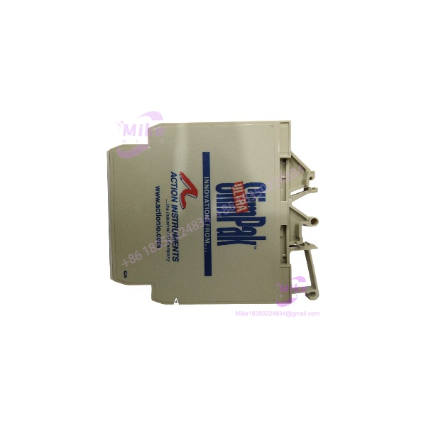
SLIMPAK G408-0001 | DC Input Signal Isolator, 1800 VDC
Dynamic Product Introduction
The SLIMPAK G408-0001 solves a very practical instrumentation problem: taking a DC field signal, isolating it from the receiving control system, and reproducing it as a clean proportional output. It is part of the Ultra SlimPak G408 family and is specifically designed as a DIN-rail-mounted DC signal conditioner with isolation between the input, output, and power supply.
That isolation is the important engineering feature. In a plant with multiple power supplies, PLC racks, transmitters, drives, and grounded instrument cabinets, an analog loop can develop ground-potential problems even when every individual device appears healthy. The G408-0001 provides a practical boundary between those circuits while also allowing the engineer to change the input and output ranges.
Unlike a fixed 4–20 mA repeater, the G408-0001 can accept a broad range of DC voltage and current inputs. Its standard-output version can be configured for 0–5 V, 0–10 V, 0–1 mA, 0–20 mA, or 4–20 mA.
G408-0001
Key Technical Specifications
- Model: G408-0001
- Series: Ultra SlimPak G408
- Function: DC input field-configurable isolator
- Input voltage ranges: 10 mV to 100 V, across multiple selectable ranges
- Input current ranges: 1 mA to 100 mA
- Output voltage: 0–5 V or 0–10 V
- Output current: 0–1 mA, 0–20 mA, or 4–20 mA
- Isolation: 1,800 VDC between input, output, and power
- Power supply: 9–30 VDC
- Typical power consumption: 1.5 W
- Maximum power consumption: 2.5 W
- Operating temperature: 0 to 55°C
- Storage temperature: -25 to 70°C
- Input voltage impedance: Greater than 100 kΩ
- Current input impedance: Approximately 20 Ω
- Voltage-output source impedance: Less than 10 Ω
- Maximum voltage-output drive: 10 mA
- 4–20 mA output compliance: Up to 12 V / 600 Ω
- 0–20 mA output compliance: Up to 12 V / 600 Ω
- 0–1 mA output compliance: Up to 7.5 V / 7.5 kΩ
- Common-mode rejection: 100 dB, DC to 60 Hz
- Response time: Approximately 200 ms, 10–90%
- Terminals: Screw terminals for 12–22 AWG
- Mounting: TS32 or TS35 DIN rail
- Approximate weight: 0.5 lb
These values are from the G408 technical documentation; the exact factory calibration should still be checked because the module is field configurable.
Global Sourcing & Live-Test SOP
1. Verify the physical identity first
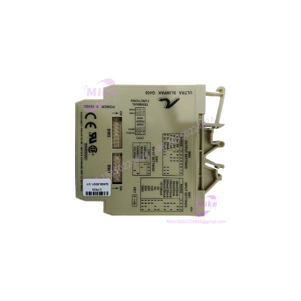
For an older G408-0001, photograph the complete label before testing. Confirm the model, revision or appended designation, terminal markings, and physical condition.
Do not confuse the standard-output with the . The latter is the bipolar-output version. The two belong to the same family but have different output capabilities.
2. Determine the installed configuration
This is the most important step.
The has multiple input-range settings selected through internal switches. Zero and span adjustments also provide substantial range flexibility. The documentation states that the standard factory preset the is:
4–20 mA input → 4–20 mA output.
However, never assume a used unit remains at that configuration. It may have been recalibrated for a completely different voltage or current range.
3. Never change configuration with power applied
The manufacturer documentation explicitly warns against changing the selector switches while the unit is powered. Disconnect power before changing configuration.
This is an important procurement-test point. A supplier should not claim that a unit was “reconfigured” unless the procedure was performed correctly.
4. Perform input/output simulation
For a typical 4–20 mA configuration, apply calibrated input values such as:
- 4 mA
- 8 mA
- 12 mA
- 16 mA
- 20 mA
Measure the isolated output at each point.
For a voltage configuration, use the applicable calibrated voltage range and repeat the same proportionality test.
Check both zero and span. A module that passes at 12 mA but has significant error at 4 or 20 mA should not be considered fully tested.
5. Verify isolation
Where appropriate laboratory equipment is available, verify insulation/isolation according to the applicable service procedure. Do not casually apply a hipot test to an unknown used module without following the manufacturer’s specified test conditions.
The documented isolation rating is 1,800 VDC between input, output, and power.
6. Check thermal stability
The original documentation recommends allowing approximately 1–2 hours for warm-up and thermal equilibrium before final calibration.
For a critical spare, I would extend this into a longer operational heat run. Monitor input/output accuracy, power consumption, and enclosure temperature.
7. Final procurement preparation
Record the tested input range, output range, calibration condition, measured errors, and configuration-switch positions.
For this particular product, a test report stating only “powers on and works” is weak evidence. The configuration is part of the product’s functional identity.
Field Engineer’s Pitfall Guide
1. Do not assuvery is still configured for 4–20 mA.
The factory default is 4–20 mA input to 4–20 mA output, but the is deliberately designed to be field configurable.
A used unit may have been configured for a voltage input, a different current range, reverse operation, or a customized zero/span relationship. Check the internal switches and calibration before installation.
2. Do not change DIP-switch settings while energized.
This is not merely a software configuration parameter. The manufacturer explicitly warns that changing the switch settings with power applied can cause severe damage.
In a maintenance environment, isolate the module before opening or reconfiguring it.
3. Do not overlook the differenceween and -1001.
The model suffix determines the output architecture. The is the standard-output model, supporting 0–5 V, 0–10 V, 0–1 mA, 0–20 mA, and 4–20 mA. The -1001 is the bipolar-output variant supporting ±5 V and ±10 V.
A visually similar module can therefore be the wrong spare even if the base designation matches.
Intent-Driven FAQ
Q: What is theMPAK used for?
A: It is a DC input field-configurable signal isolator and conditioner. It can accept DC voltage or current signals, isolate them from the output and power circuits, and produce a proportional standard output.
Q the a PLC analog input module?
A: No. It is an independent DIN-rail signal-conditioning device. It can sit between a transmitter, sensor, PLC, DCS, controller, or other analog equipment to provide signal conversion and electrical isolation.
Q: What is the isolation rating?
A: The published specification is 1,800 VDC between input, output, and power.
Q: What is the standard factory calibration?
A: The documented standard factory setting for is 4–20 mA input and 4–20 mA output. A used unit should still be checked because field configuration and calibration can change that setting.
Can accept a voltage input?
A: Yes. The input section supports selectable voltage ranges extending from approximately 10 mV to 100 V, in addition to multiple current-input ranges.
Q: What output ranges are avaie on ?
A: The standard-output model supports 0–5 V, 0–10 V, 0–1 mA, 0–20 mA, and 4–20 mA. Bipolar ±5 V and ±10 V outputs belong to the -1001 variant.
Q: the be hot-swapped?
A: Do not assume so. The module is powered from 9–30 VDC and its configuration switches must not be changed while energized. Follow the installed control-system isolation procedure before removing, installing, or reconfiguring the unit.
Q: What should I request when buyinused ?
A: Request clear photos of the actual model label, terminal condition, internal configuration if available, and a test report showing the configured input/output range. For a 4–20 mA application, a useful report should show multiple measured points rather than simply confirming that the LED illuminates.
Procurement Verdict
The is a compact, flexible solution for DC analog signal isolation and conditioning, particularly where ground-loop elimination, signal conversion, and DIN-rail installation are required.
Its strongest procurement advantage is also its biggest testing concern: field configurability. Two unitrked may have different internal input ranges or calibration settings. Treat the configuration as part of the functional specification.
For a production spare, I would prioritize exact model verification, switch-position documentation, calibrated I/O testing, isolation verification, and a documented heat run. If the application is standard 4–20 mA, confirm both ends of the loop rather than assuming the factory default remains intact.





