


Description
SIGMATEK DNC115 | C-DIAS Positioning Module Core Category
Dynamic Product Introduction
Achieving tight mechanical tolerances in modern high-speed packaging or handling lines demands absolute zero-latency feedback from physical motion axes. Integrating the SIGMATEK DNC115 directly into the C-DIAS backplane provides machine builders with a dedicated hardware engine capable of parsing high-frequency pulse trains without loading the primary CPU core. Unlike generalized multi-purpose I/O blocks, this specialized module handles differential encoder signals with microsecond precision, ensuring smooth acceleration profiles and repeatable positioning across repetitive tooling cycles.
In field deployments, dropping the DNC115 into an existing rack instantly stabilizes drift-prone analog reference loops. The unit blends rugged optical isolation on its digital switching channels with a compact footprint, keeping control cabinet layouts tidy while eliminating cross-talk from neighboring high-power drives.
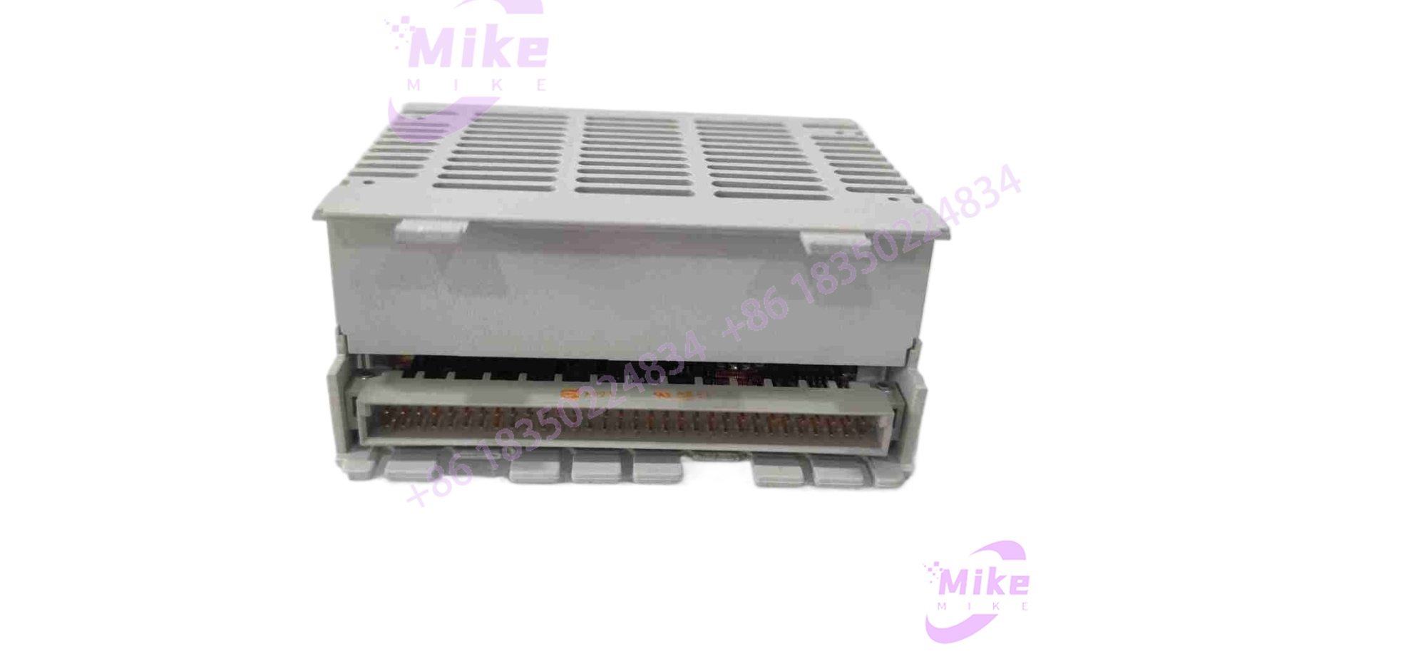
DNC115
Key Technical Specifications
| Core Parameter | Technical Specification |
| Supported Architecture | C-DIAS Bus Modular System |
| Encoder Input Channel | 1-Channel Incremental (A, /A, B, /B, R, /R) |
| Input Signal Level | RS422 Differential Level (150Ω load) |
| Max Counter Frequency | Up to 500 kHz (4-times evaluation) |
| Analog Output | 1 Channel (-10V to +10V DC, 12-bit resolution) |
| Digital Inputs | 3 Channels (+24V DC, reference/limit switching) |
| Digital Outputs | 3 Channels (Opto-isolated, max 30V DC / 100mA) |
| Module Supply Voltage | 18V to 30V DC |
| Operating Temperature | 0°C to +60°C |
| Enclosure Protection | IP20 (Requires DKL terminal module) |
Global Sourcing & Live-Test SOP (Transparency Core)
Procuring legacy or replacement motion hardware requires strict validation protocols to guarantee performance on high-speed industrial lines. Our workflow ensures complete operational readiness:
- Inbound Verification: Every DNC115 module is inspected for physical board integrity, matching laser-engraved serial numbers against original factory shipment logs and checking for electrostatic discharge (ESD) protection compliance.
- Live Simulation: Technicians seat the unit onto an active C-DIAS test rack powered by standard cabinet rails to verify proper bus communication handshakes.
- Diagnostics: Using high-resolution function generators and digital multimeters (such as Fluke bench meters), engineers inject simulated RS422 encoder pulses up to 500 kHz to test counter accuracy. The -10V to +10V analog output undergoes linearity checks, followed by a continuous 24-hour thermal soak test.
- Final Prep: The unit’s hardware revision is logged, terminal connectors are cleared of debris, and the module is sealed inside moisture-barrier anti-static bags.
The Field Engineer’s Pitfall Guide
❗ Neglecting Shield Grounding on Encoder Lines: Leaving encoder cable shields ungrounded or improperly terminated at the DNC115 terminal block invites electromagnetic interference (EMI). I’ve seen erratic positioning jumps occur simply because a technician stripped back too much shielding braid near the entry gland.
❗ Exceeding Digital Output Current Limits: The onboard opto-isolated outputs are strictly rated for low-current control signals (max 100mA). Hooking them directly up to a small external relay coil without an intermediate interposing cube will fry the optical coupler instantly.
❗ Hot-Plugging onto an Active Backplane: Inserting or pulling the DNC115 while the C-DIAS rack is powered can corrupt bus synchronization. Always drop main cabinet power before swapping modules to protect the internal data pins.
Intent-Driven FAQ
Will swapping the erase my axis motion parameters or machine program?
No. Axis configuration parameters and control logic reside in the central CPU or system memory project file rather than on this localized I/O module, though you should verify scaling factors match the hardware revision.
Can the handle absolute encoders, or is it strictly incremental?
The module is designed specifically for incremental encoder signals (RS422 differential levels with channels A, B, and reference marker R). It does not natively process absolute serial protocols like SSI or EnDat without a separate interface variant.
What terminal block is required to interface external wiring with this module?
The unit typically pairs with a matching terminal module (such as the DKL series, e.g., DKL 053), which handles the physical spring-clamp connections for the field wiring.
What kind of warranty is provided with surplus or replacement units?
Verified replacement units typically carry a comprehensive 365-day operational warranty covering electronic component failure and workmanship defects.
How can I troubleshoot a sudden position-loss error code on this axis?
Check the front-panel status LEDs to confirm bus power and signal health. If LEDs are normal, use an oscilloscope to verify that the incoming encoder differential pairs aren’t suffering from signal attenuation or noise corruption.





