


Description
Siemens 6GT2001-0AA00 | MOBY E SLG 41 Read/Write Head In Stock
Architect’s Product Breakdown
The Siemens 6GT2001-0AA00 (designated as the SLG 41) is a compact, heavy-duty RFID read/write antenna from the classic MOBY E family. Engineered for harsh industrial environments, the SLG 41 communicates with MOBY E transponders via inductive coupling, transmitting power and bidirectional data blocks across an air gap of up to 100 mm.
Unlike modern standard ISO 15693 readers, MOBY E hardware utilizes proprietary Siemens communication protocols tuned for high-speed dynamic tracking on conveyor systems, pallet transport lines, and automotive assembly skids. The unit connects directly to upstream MOBY interface modules (such as ASM 452, ASM 473, or ASM 475) via dedicated shielded multi-conductor antenna cables, which pass raw high-frequency data signals to the controller without onboard protocol translation overhead.
Because the MOBY E product family is phased out, replacing an SLG 41 requires matching exact antenna inductances and carrier frequency response. Drop-in replacement with the original 6GT2001-0AA00 prevents transmission field distortion, tag read failures, and communication timeouts on existing PLC logic blocks (e.g., FC45 / FB45).
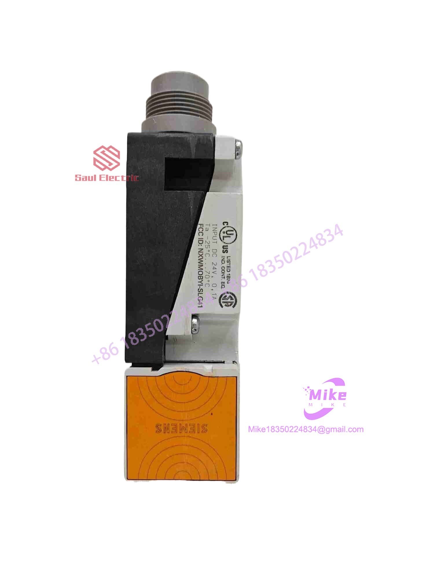
6GT2001-0AA00
Key Technical Specifications
| Parameter | Technical Specification |
| Manufacturer | Siemens AG |
| Product Line | MOBY E RFID System |
| Model / Type | SLG 41 Read/Write Head |
| Operating Frequency | 13.56 MHz (Inductive Coupling) |
| Operating Range | Up to 100 mm (depending on transponder model and mounting surface) |
| Compatible Transponders | MOBY E Data Carriers (MDS E600, MDS E611, MDS E623, etc.) |
| Interface / Connection | 6-pin Threaded Connector (for cable to ASM Interface Module) |
| Status Display | Built-in LED Indicators (Power / Tag Present / Read-Write Error) |
| Protection Rating | IP67 Heavy-Duty Industrial Plastic Enclosure |
| Operating Temperature | -25°C to +70°C (-13°F to 158°F) |
Field Engineer’s Pitfall Guide (Unique Value)
- MOUNTING DIRECTLY ON METAL WITHOUT CLEARANCE: Never recess the active antenna surface flush into steel frames. Metal surrounding the SLG 41 housing detunes the 13.56 MHz inductive antenna coil, severely shrinking the read distance or rendering tags completely unreadable. Always maintain a minimum metal-free clearance zone of at least 20–30 mm around the sides of the sensing face.
- CROSS-TALK BETWEEN ADJACENT READ HEADS: Do not mount two 6GT2001-0AA00 heads too close together. If two SLG 41 readers operate within 0.5 to 1 meter of each other without physical shielding, their electromagnetic fields will overlap. This field interference causes mutual signal suppression and intermittent “Tag Communication Error” faults on the ASM interface module.
- HOT-PLUGGING CABLES TO THE ASM MODULE: Always isolate power to the ASM interface unit before disconnecting the SLG 41 antenna cable. Disconnecting the 6-pin threaded connector while the antenna drive circuit is active can cause high-frequency voltage spikes that burn out the sensitive RF front-end stages on the reader’s mainboard.
QA & Testing SOP (Transparency)
- Visual & Structural Audit: Microscopic inspection of the plastic housing, mounting screw holes, O-ring seal, and 6-pin connector contacts for corrosion or pin misalignment.
- RF Field & Carrier Frequency Test: Inductive field output verified at 13.56 MHz using an RF spectrum analyzer coil to ensure output power and frequency tuning are within factory tolerances.
- Live Tag Read/Write Functional Testing: Connected to an active ASM 475 module in an S7-300 rack; multiple MOBY E transponders (MDS E-series) passed through the sensing field to verify static and dynamic read/write data operations.
- Thermal & Vibration Stress Check: Operates under continuous cyclical read/write operations for 4 hours to confirm long-term thermal stability and field consistency.
- Clean Baseline & Anti-Static Packaging: Protective connector caps applied, unit wrapped in anti-static ESD shielding, and packed inside custom foam-lined shipping boxes.
Technical FAQ
Is the 6GT2001-0AA00 (MOBY E SLG 41) compatible with newer RF200 or RF300 tags?
No. The SLG 41 uses the proprietary MOBY E protocol on 13.56 MHz. It cannot read or write to SIMATIC RF200/RF300 ISO 15693 or ISO 14443 tags. It must be paired specifically with MOBY E series transponders (MDS E-series).
What is the maximum cable length allowed between the SLG 41 and the ASM interface module?
The maximum recommended antenna cable length is 100 meters, using pre-assembled, double-shielded Siemens MOBY cables. Exceeding this distance causes signal attenuation and timing skew along the high-frequency line.
What should I do if the “PRESENCE” LED lights up, but the PLC reports a read error?
A lit PRESENCE LED indicates the reader detects a transponder in its magnetic field, but data transfer failed. This usually points to electromagnetic noise from nearby VFDs, incorrect address positioning in your PLC read function call, or a damaged memory sector on the transponder itself.
Can I replace the SLG 41 with an SLG 42 or SLG 43?
While they belong to the same MOBY E family, different SLG models have different physical footprints, antenna geometry, and maximum read ranges. Replacing an SLG 41 with another model requires reviewing mechanical clearance and re-evaluating the conveyor timing and tag position windows in your PLC logic.
Does the SLG 41 require any parameterization or firmware downloads?
No. The SLG 41 is a hardware antenna and driver head. All configuration parameters (such as data block sizes, tag types, and operating modes) are stored and managed directly inside the connected ASM interface module (e.g., ASM 452 / ASM 475) or the PLC software blocks.





