


Description
OLEC 64VB412V02 | Industrial Lamp Control Subassembly
Dynamic Product Introduction
Lamp flicker, arc ignition failures, and sudden exposure shut-offs on legacy OLEC UV systems typically stem from degraded power supply ballast boards or exhausted filtering capacitors rather than burner tube burnout. When an older exposure unit starts dropping UV intensity or failing to maintain stable lamp current, adjusting external controls rarely compensates for fundamental internal component drift. Deploying the OLEC 64VB412V02 resolves this reliability bottleneck directly, providing an OEM-spec replacement assembly engineered to restore precise optical power regulation.
In critical manufacturing refits, sliding in this exact replacement module restores uniform exposure cycles without requiring an expensive, full-scale exposure system redesign. (Though verifying input line voltages and internal transformer tap settings prior to energization remains essential.) It handles severe electrical and thermal loads cleanly, keeping legacy photolithography and curing assets running dependably.
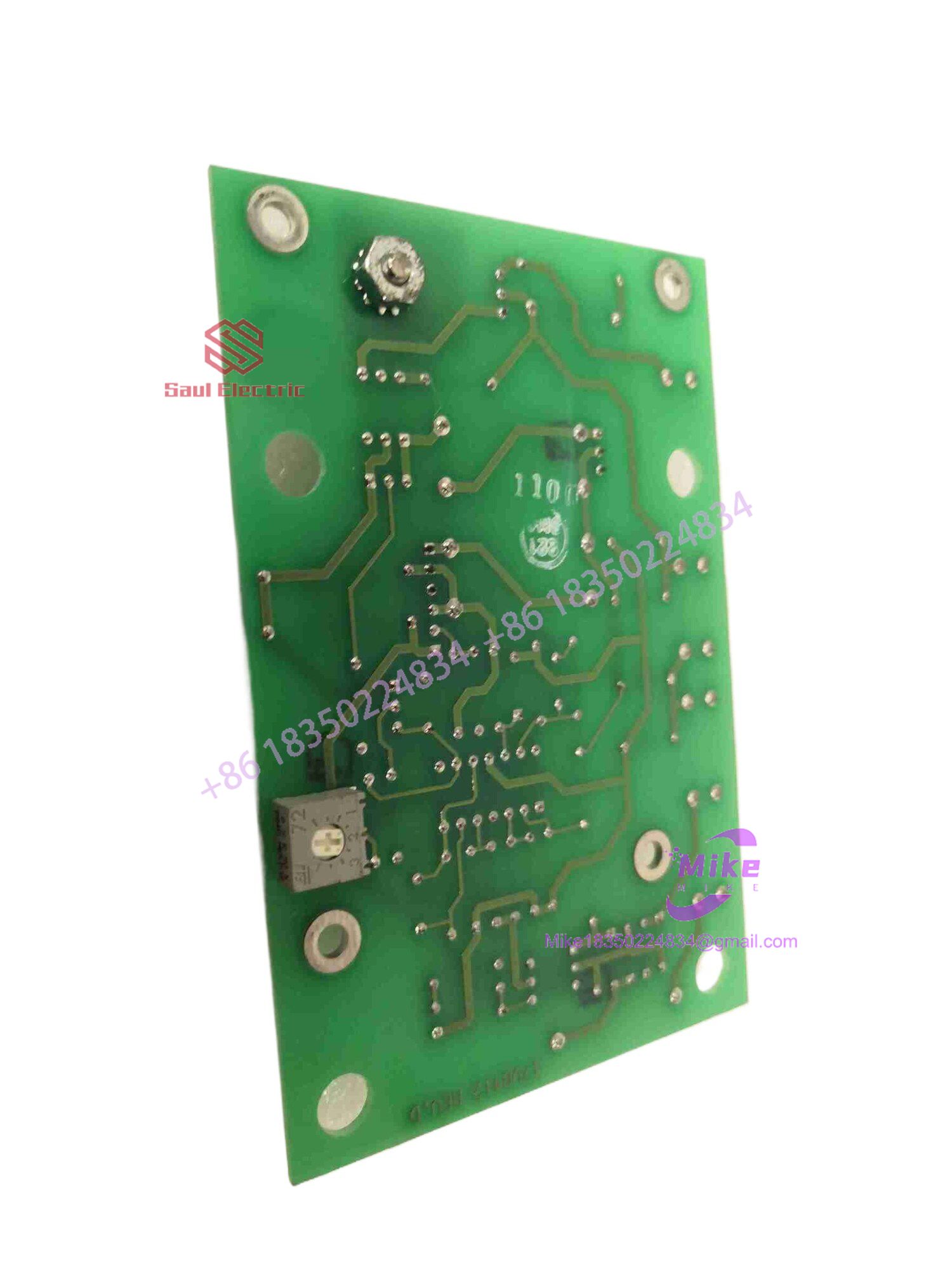
64VB412V02
Key Technical Specifications
| Technical Parameter | Specification Detail |
| Device Category | UV Lamp Ballast / Power Supply Assembly |
| Series Compatibility | OLEC Industrial UV Exposure Systems |
| Cooling Requirements | Forced-air or convection cabinet design (dependent on enclosure) |
| Operating Environment | Industrial exposure tool electronics chassis |
| Ambient Operating Temp | 0^\circC to 50^\circC |
| Terminal Architecture | Heavy-duty industrial screw terminals and quick-disconnect plugs |
| Enclosure Type | Open-frame industrial circuit board with rigid mounting chassis |
Global Sourcing & Live-Test SOP (Transparency Core)
Procuring legacy high-voltage UV power electronics demands rigorous electrical testing to ensure safe arc ignition and stable continuous-load output.
- Inbound Verification: Incoming subassemblies undergo comprehensive serial tracking, OEM label validation, and anti-counterfeit component dating against historic OLEC records.
- Live Simulation: Qualified ballast modules are mounted onto an authentic lamp test rig powered by monitored AC lines to evaluate strike voltage, arc stability, and thermal performance.
- Diagnostics: Technicians execute high-voltage insulation tests, capacitor ripple checks, and full-load thermal soak sweeps to isolate latent semiconductor or transformer failure risks.
- Final Prep: Terminal blocks are cleaned to remove oxidation, and the unit is sealed inside heavy-duty multi-layer shielding and shock-absorbent packaging.
The Field Engineer’s Pitfall Guide
❗ High-Voltage Stored Energy Hazards: Capacitors within UV ballast assemblies can retain lethal DC voltages long after input power is disconnected. Always verify complete capacitor discharge with a meter before servicing.
❗ Transformer Tap Mismatches: Failing to verify input power tap settings against your facility’s actual line voltage can cause severe over-voltage stress on internal components during startup. Always cross-check wiring taps against schematics.
❗ Inadequate Cabinet Airflow: Operating replacement power assemblies in an enclosure clogged with dust or lacking proper exhaust ventilation will trigger thermal overload shutdowns. Ensure clean cooling paths prior to commissioning.
Intent-Driven FAQ
Will this power assembly drop directly into my existing OLEC exposure system chassis?
Yes, the 64VB412V02 matches standard OLEC mechanical mounting dimensions and electrical pinouts, ensuring seamless physical integration.
Are these legacy power supplies factory sealed or certified surplus stock?
We maintain strict inventories of both factory-sealed surplus hardware and fully recertified, bench-tested units. Each listing explicitly details the precise condition tier to match your facility standards.
What causes premature failure in legacy UV exposure power supplies?
Component aging is typically driven by continuous exposure to high thermal loads, electrolytic capacitor drying, and electrical stress from repetitive lamp ignition cycles.
What kind of warranty coverage is included with this replacement part?
Every unit is backed by our comprehensive operational warranty, covering electrical component health, transformer integrity, and functional performance from day one.
Do I need to recalibrate light intensity meters after installation?
While the electrical ballast regulates power output directly, performing a standard radiometer check to verify consistent UV energy dosage on the work plane during initial startup is recommended.





