

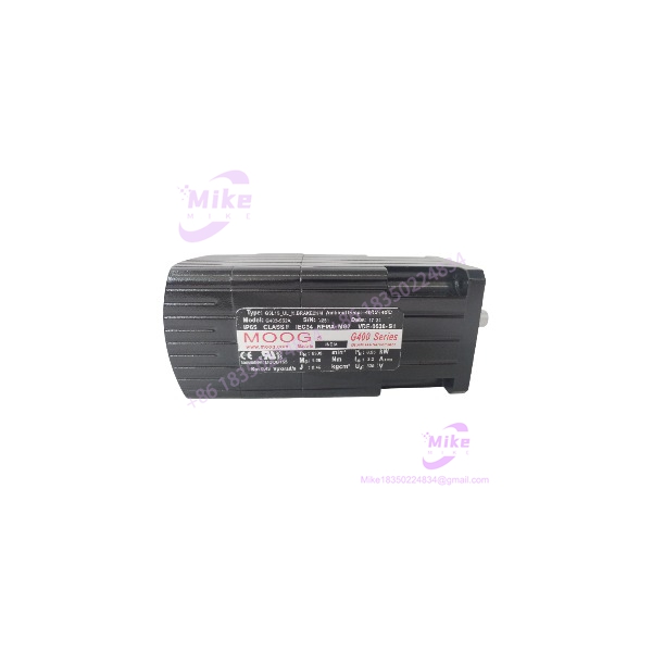
Description
Moog G403-552A | Industrial Servo Motor Replacement
Dynamic Product Introduction
The Moog G403-552A belongs in the category of components where the nameplate matters more than a generic product description. It is identified across industrial procurement sources as a Moog servo motor, with listings associating the part with the G400 family.
For a maintenance engineer, that means the G403-552A should be treated as a matched electromechanical component—not simply as a motor with the same mounting envelope. Servo performance depends on the relationship between the motor windings, feedback device, amplifier current loop, commutation parameters, mechanical load, and tuning values.
This is particularly important when replacing an older production motor. A motor can spin correctly at no load and still be unsuitable for the installed servo amplifier. (That is one of the classic mistakes in legacy motion-system procurement.)
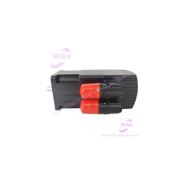
G403-552A
Key Technical Specifications
- Manufacturer: Moog
- Model: G403-552A
- Product type: Servo motor
- Motor family: G400-series, according to industrial product references
- Motor construction: Brushless AC servo motor
- Application: Closed-loop industrial motion control
- Feedback: Verify exact encoder/resolver configuration from the physical nameplate
- Motor winding: Verify exact winding code before substitution
- Drive interface: Requires a compatible servo amplifier/drive
- Mechanical interface: Verify flange, shaft, mounting-hole pattern, and shaft dimensions against the existing motor
- Electrical interface: Verify phase and feedback connector pinout before energization
- Rated speed: Do not rely on generic marketplace figures; confirm the exact motor nameplate/datasheet
- Rated torque/power: Verify against the exact motor revision
- Brake: Do not assume a brake is fitted unless the nameplate or physical inspection confirms it
- Feedback polarity/offset: Must be confirmed during commissioning
- Cooling: Verify the installed motor’s cooling arrangement and application requirements
Some secondary listings claim an 8,000 RPM maximum speed, approximately 0.95 kW rated power, 325 VDC drive voltage, and IP65 protection. Those figures are not sufficiently corroborated by an OEM Moog document available in the search results, so they should be treated as listing-specific claims, not universal G403-552A specifications.
Global Sourcing & Live-Test SOP
1. Inbound identity verification
Before any electrical testing, photograph the complete nameplate. Record:
- G403-552A model designation
- Serial number
- Winding or configuration suffixes
- Feedback designation
- Brake designation, if present
- Connector markings
- Manufacturing information
Do not accept a supplier statement that a visually similar G403-series motor is interchangeable.
2. Mechanical inspection
Check the shaft for scoring, corrosion, fretting, or impact damage. Inspect the flange and mounting holes for deformation. Rotate the shaft manually and listen for bearing roughness.
A clean housing does not prove a healthy motor. Bearing condition and rotor position feedback are much more important to actual machine performance.
3. Winding verification
With the motor electrically isolated, measure phase-to-phase resistance and compare all phases. Large imbalance is a reason to stop the test rather than proceed to drive commissioning.
Where the applicable Moog procedure specifies insulation testing, use the appropriate test voltage and limits. Do not improvise a high-voltage insulation test on an unknown feedback assembly.
4. Feedback verification
Identify the installed feedback technology before connecting it to the amplifier. Check connector pinout, continuity, shield integrity, and feedback signal behavior using the correct test equipment.
A servo motor can have electrically healthy windings while its feedback circuit is defective. The drive may then report commutation, overspeed, following-error, or encoder/resolver faults immediately after enable.
5. Drive compatibility check
Compare the motor against the existing amplifier parameters before applying full power.
Verify:
- Motor winding configuration
- Rated current
- Feedback type
- Feedback polarity
- Commutation information
- Current-loop settings
- Velocity-loop settings
- Maximum permitted speed
- Brake configuration, if applicable
Do not perform an automatic motor-identification routine unless the connected drive explicitly supports the motor and the machine OEM permits it.
6. Controlled commissioning
Begin with the mechanical load in a safe condition. Verify feedback direction at low speed before allowing the machine to accelerate.
A sensible commissioning sequence is:
- Control-power verification
- Feedback recognition
- Low-current enable
- Low-speed jog
- Direction verification
- Current/torque observation
- Servo following-error check
- Acceleration test
- Load test
- Extended heat run
7. Final 24-hour test
For a critical spare, operate the motor/drive combination under representative conditions for an extended period. Monitor motor temperature, vibration, current balance, feedback stability, and drive fault history.
The objective is not merely to prove that the shaft turns. The objective is to establish that the motor behaves predictably inside the intended closed-loop system.
Field Engineer’s Pitfall Guide
1. Do not con the with a generic brushless motor.
A standard three-phase motor can have similar power connections and still be completely unsuitable for a servo application.
The servo amplifier expects specific electrical and feedback characteristics. Current-loop tuning, commutation, feedback scaling, and mechanical inertia all matter. A motor swap without parameter verification can produce excessive current, unstable velocity control, or immediate drive faults.
2. Never assume the published marketplace specifications are complete.
Current online listings disagree on important details such as rated speed, power, voltage, feedback technology, brake configuration, and environmental rating. For example, one listing describes an encoder-based motor with 325 VDC drive voltage and 8,000 RPM maximum speed, while another gives different configuration information.
That is exactly why the ical nameplate and original machine documentation should control the procurement decision.
3. Verify the mechanical and feedback interfaces separately.
A motor can physically bolt into the machine and still fail integration because the shaft dimensions, feedback connector, resolver/encoder configuration, or winding characteristics differ.
I have seen replacement-motor troubleshooting become unnecessarily complicated because the engineering team checked only the flange and shaft. For a servo system, the electrical identity is just as important as the mechanical identity.
Intent-Driven FAQ
Q: What is Moog ?
A: The is identified as a Moog servo motor, with multiple industrial procurement sources associating it with the G400-series motor family.
Q the a servo amplifier or servo valve?
A: The is identified as a servo motor. Do not confuse it with Moog’s G122-829A001 servo amplifier or Moog’s D-series/G-series hydraulic servo valves.
Q: Can I replace another -series mototh a ?
A: Not automatically. Verify the complete model designation, winding configuration, feedback type, shaft/interface dimensions, and amplifier compatibility. A shared family designation does not by itself establish electrical interchangeability.
Q: Dovery have an encoder?
A: Do not assume that from secondary listings. Some current listings describe encoder feedback, while other sources do not provide enough information to establish the feedback configuration for every unit. Confirm the exact nameplate and connector configuration of the motor being purchased.
Q: What should I test oused ?
A: At minimum, inspect the shaft and bearings, measure phase-to-phase winding consistency, check insulation according to the applicable procedure, verify the feedback circuit, inspect connectors, and perform a controlled drive test. For a critical spare, an extended loaded test is preferable.
Q the a drop-in replacement?
A: Only when the complete motor identity and mechanical/electrical configuration match the installed unit. A matching base model alone is insufficient evidence for a drop-in replacement.
Q: What should I request when purchasing a factory-sealed osted ?
A: Request photographs of the actual nameplate, complete model number, serial/configuration information, physical connector arrangement, condition of the shaft, and a documented test report. For used equipment, ask specifically whether winding balance and feedback operation were tested.
Procurement Verdict
The should be sourced as a specific servo-motor assembly, not as a generic brushless motor. Current procurement evidence consistently identifies the part as a Moog servo motor, but publicly available secondary listings contain conflicting technical specifications.
For an industrial replacement, the safe procurement hierarchy is:
Exact nameplate → winding/configuration → feedback type → mechanical interface → compatible amplifier → tested operation.
If the existing motor is still installed, photograph its complete nameplate before ordering the spare. That single step can prevent an expensive mismatch in feedback, winding, or drive parameters.





