

Description
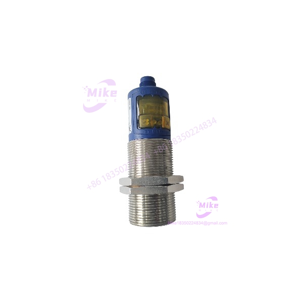
microsonic mic+130/IU/TC | M30 Ultrasonic Sensor
Product Introduction
The microsonic mic+130/IU/TC is an M30 cylindrical ultrasonic sensor designed for contactless measurement of the distance between the sensor and a target. It uses echo propagation-time measurement at 200 kHz, with a 200 mm blind zone, 1,300 mm operating range, and 2,000 mm maximum range.
For PLC and process-control applications, the sensor provides a configurable analog measurement signal of 4–20 mA or 0–10 V and operates from 9–30 VDC. The integrated 3-digit LED display and two-button TouchControl interface allow local teach-in and numerical configuration, while synchronization and multiplex functions support installations containing multiple compatible ultrasonic sensors.
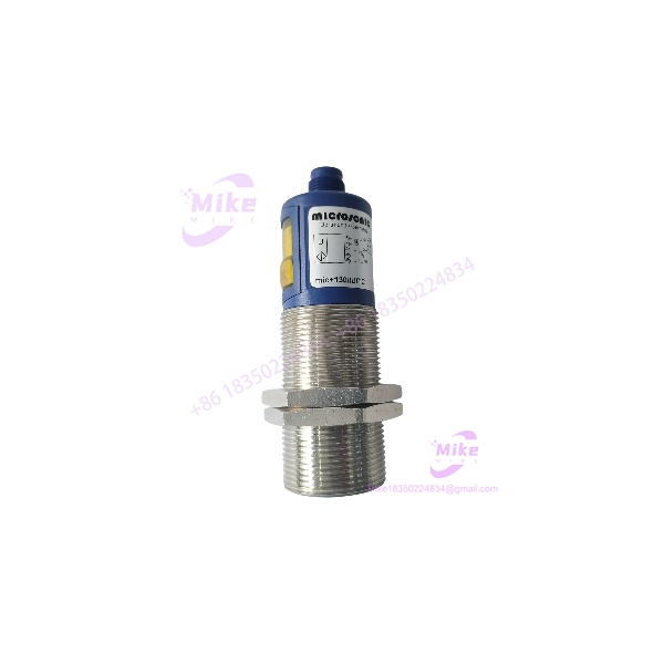
MIC+130/IU/TC
Key Technical Specifications
- Manufacturer: microsonic
- Product: mic+130/IU/TC
- Sensor Family: mic+
- Design: Cylindrical M30
- Measurement Principle: Ultrasonic echo propagation time
- Transducer Frequency: 200 kHz
- Blind Zone: 200 mm
- Operating Range: 200–1,300 mm
- Maximum Range: 2,000 mm
- Resolution: 0.18–0.57 mm, depending on configured analog window
- Reproducibility: ±0.15%
- Accuracy: ±1%, with internal temperature-drift compensation
- Supply Voltage: 9–30 VDC
- Voltage Ripple: ±10%
- No-Load Current: ≤80 mA
- Analog Output: 4–20 mA / 0–10 V
- Output Characteristic: Rising or falling, configurable
- Connection: 5-pin M12 initiator connector
- Response Delay: 92 ms
- Availability Delay: <300 ms
- Housing Protection: IP67
- Operating Temperature: -25°C to +70°C
- Storage Temperature: -40°C to +85°C
- Housing Material: Nickel-plated brass sleeve with PBT/TPU plastic components
- Display: 3-digit LED
- Controls: 2 push-buttons with TouchControl
- Temperature Compensation: Yes
- Synchronization: Yes
- Multiplexing: Yes
- Weight: Approximately 150 g
These values are taken primarily from microsonic’s current product documentation. An older catalog reports a lower 110 g weight and a 110 ms response time, so the current manufacturer page should take precedence when preparing a technical specification.
Application Scenarios & Pain Points
1. PLC-Based Distance Measurement
The analog output can provide a continuous distance signal to a PLC analog input for machine-position monitoring.
Engineering consideration: Confirm whether the PLC analog input is configured for current or voltage before wiring. The sensor supports 4–20 mA or 0–10 V, with voltage output requiring a supply of at least 15 VDC.
2. Product Position and Presence Detection
The ultrasonic measurement principle allows non-contact detection of products without requiring optical contrast or a physical switch.
Pain point: Target geometry and the ultrasonic detection zone still matter. A nominal 2,000 mm maximum range does not mean every target can be reliably measured at that distance.
3. Tank and Material Level Monitoring
The sensor can be used for non-contact level measurement where the material surface provides an adequate ultrasonic echo.
Pain point: Foam, turbulent surfaces, angled surfaces, vapor, and other acoustic conditions can affect echo quality. The actual installation should be validated at the required measurement distance.
4. Loop and Web-Control Applications
The analog output can be used to provide continuous position information for material-handling or web-control equipment.
Engineering consideration: The published 92 ms response delay must be considered when evaluating the sensor in a high-speed control loop.
5. Machine Height and Width Measurement
The 0.18–0.57 mm resolution range, depending on the configured analog window, can support dimensional measurement applications where the target and installation geometry are appropriate.
QA & Live Testing SOP
1. Identity Verification
Before accepting the unit:
- Photograph the complete product label.
- Confirm microsonic mic+130/IU/TC.
- Verify that the unit is not the
/Estainless-steel variant. - Record serial/product identification if present.
- Confirm the physical connector is the specified 5-pin M12 configuration.
- Check the housing and sensing face for damage.
The manufacturer identifies mic+130/IU/TC/E separately as a further stainless-steel version. Do not substitute the suffix /E into the standard product description.
2. Mechanical Inspection
Inspect:
- M30 threaded body.
- Sensor face and ultrasonic transducer.
- M12 connector.
- Connector threads.
- Housing for impact or corrosion.
- Mounting threads.
- Display window.
- Push-buttons.
Do not apply excessive mechanical force to the transducer face.
3. Electrical Test
Use a regulated DC supply within the specified 9–30 VDC range.
Verify:
- Correct supply polarity.
- Startup behavior.
- LED display operation.
- TouchControl button response.
- Current consumption.
- Analog output.
- Output response to changing target distance.
The device includes reverse-polarity protection, but correct wiring should still be verified before energization.
4. Analog Output Test
Place a suitable target at several controlled distances within the usable measurement window.
Record:
- Measured physical distance.
- Sensor display value.
- 4–20 mA output.
- 0–10 V output where applicable.
- Output linearity.
- Response to increasing distance.
- Response to decreasing distance.
Verify that the configured rising/falling characteristic corresponds to the intended PLC scaling.
5. Ultrasonic Functional Test
Test multiple target distances rather than relying on a single point.
Recommended checkpoints:
- Approximately 200–300 mm.
- Mid-range target.
- Approximately 1,000 mm.
- Near the required application limit.
- Target removal/no-echo condition.
Record unstable readings, missed echoes, excessive fluctuation, or unexpected output behavior.
6. Packaging
- Protect the ultrasonic sensing face from impact.
- Protect the M12 connector from bending or contamination.
- Use ESD-conscious handling around the electronics.
- Prevent the M30 threaded body from striking other components.
- Use cushioning that prevents movement during shipment.
Field Engineer’s Pitfall Guide
❗ Do not confuse operating range with maximum range. The manufacturer lists a 200–1,300 mm operating range and 2,000 mm maximum range. Application validation should be based on the actual target and detection conditions.
❗ The 200 mm blind zone is significant. A target closer than the specified blind zone should not be assumed to produce a valid measurement.
❗ Do not wire the analog output based only on the product name. The sensor supports 4–20 mA and 0–10 V, and the voltage output requires UB ≥15 V. Confirm the PLC input type and sensor wiring before commissioning.
❗ Allow for the response delay. The manufacturer specifies approximately 92 ms response delay. This can matter when the sensor is incorporated into a fast position-control or registration loop.
❗ Do not confuse mic+130/IU/TC with mic+130/D/TC. The /IU/TC version is an analog-output sensor, while the /D/TC version uses a PNP switching output. They are not interchangeable simply because both use the M30 mic+130 housing family.
❗ Do not confuse the standard unit with /E. The manufacturer identifies mic+130/IU/TC/E as a separate stainless-steel version. Verify the exact suffix on the physical unit when matching an existing machine.
Intent-Driven FAQ
Q: What is the microsonic mic+130/IU/TC?
A: It is a cylindrical M30 ultrasonic distance sensor for contactless analog distance measurement. It uses a 200 kHz ultrasonic transducer and provides a 4–20 mA / 0–10 V analog output.
Q: What is the measuring range of the mic+130/IU/TC?
A: The specified measuring range is 200–2,000 mm, with a published operating range of 200–1,300 mm.
Q: What analog outputs are available?
A: The sensor provides 4–20 mA or 0–10 V analog output. The voltage output is specified for supply voltages of at least 15 VDC.
Q: What power supply does the mic+130/IU/TC require?
A: It operates from 9–30 VDC and includes reverse-polarity protection.
Q: What connector does this ultrasonic sensor use?
A: The documented connection is a 5-pin M12 initiator connector.
Q: Does the mic+130/IU/TC have a display?
A: Yes. It has a 3-digit LED display with two push-buttons for TouchControl configuration and teach-in functions.
Q: Is the mic+130/IU/TC suitable for outdoor or washdown environments?
A: The housing is rated IP67, with a specified operating temperature of -25°C to +70°C. Actual suitability depends on the mechanical installation, connector sealing, target conditions, and exposure environment.
Q: Does this sensor support synchronization?
A: Yes. The manufacturer specifies both synchronization and multiplexing functions for this model.
Q: How accurate is the mic+130/IU/TC?
A: The published accuracy is ±1%, with internal temperature-drift compensation. Reproducibility is specified as ±0.15%.
Q: Is mic+130/IU/TC interchangeable with mic+130/D/TC?
A: No. The /IU/TC model is configured for analog distance measurement, while /D/TC uses a PNP switching output. Verify the complete model designation before replacement.
Q: What condition should be specified when sourcing this sensor?
A: Unless inspection evidence is supplied, specify Legacy / Verify Condition and require label verification, housing inspection, power-up testing, display verification, and analog-output testing before acceptance.





