


Description
Lam 810-073479-215 | Chamber System Distribution Board
Dynamic Product Introduction
Chasing an intermittent chamber safety trip across an active etch line usually leads straight back to signal integrity breakdown inside the distribution stack. When a distribution board like the Lam 810-073479-215 experiences thermal degradation or line-filter failure, the tool’s primary software loses clear visibility into critical vacuum line states, position switches, and valve outputs. This board serves as a primary signal conditioning bridge on 2300-series platforms, taking raw discrete wiring inputs from surrounding process hardware and normalizing them for transmission back to the central rack controller.
Unlike basic passive terminal strips, the -215 layout incorporates targeted line-filtering banks and surface-mount protection diodes engineered to withstand high-RF noise environments typical of plasma etch chambers. Installing a fully verified 810-073479-215 board resolves chronic comms timeouts, stops false interlock trips during rapid recipe execution, and prevents subtle noise coupling from compromising delicate telemetry lines.
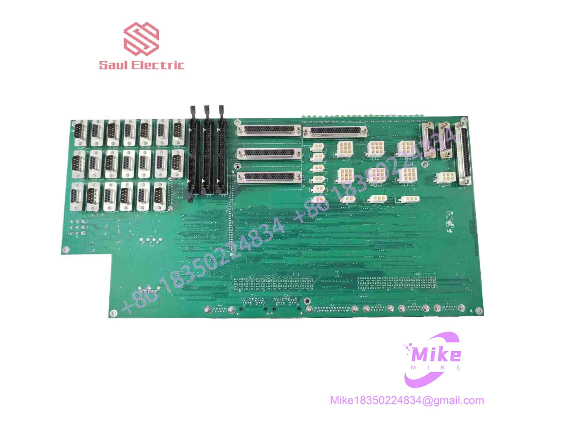
810-073479-215
Key Technical Specifications
| Parameter | Specification / Threshold |
| Part Number | 810-073479-215 |
| Board Function | System Distribution & Signal Interface PCB |
| OEM Manufacturer | Lam Research Corporation |
| Platform Support | Lam 2300, Kiyo, Vector Etch & Deposition Systems |
| Input Voltages | 24 VDC (Driver & Logic Power Distribution Rails) |
| Interfacing Connectors | Multi-pin Sub-D connector array + high-density ribbon/header sockets |
| Signal Filtering | Onboard RC noise suppression networks & transient voltage diodes |
| Mounting Style | Card rack / electronics bay standoff mounting |
| Operating Temp Range | 10°C to 50°C (Rack interior ambient limit) |
| Coating Rating | Full industrial conformal coating against humidity and process gas trace exposure |
Global Sourcing & Live-Test SOP (Transparency Core)
Re-entering surplus hardware into high-throughput fab lines requires rigorous, zero-defect quality control. Every incoming 810-073479-215 undergoes our standardized four-tier validation workflow before entering ready-to-ship inventory:
- Optical Inspection & Hardware Audit:
- Microscopic scan of every Sub-D connector pin, ribbon header, and surface-mount array to detect solder degradation, bent pins, or trace lifting.
- Audit of onboard passive components to confirm zero signs of overheating or dialectic swelling.
- Serial number tracking and revision verification against OEM change notices.
- Continuity & DC Power Isolation Run:
- Point-to-point pin continuity checks across all discrete signal channels to rule out internal layer opens or adjacent trace shorts.
- Powering the logic and driver rails on a dedicated bench fixture to verify stable DC distribution and measure quiescent current draw.
- Active Signal Loopback & Environmental Burn-in:
- Plugging the board into a simulated Lam 2300 rack harness setup.
- Exercising all discrete input and output channels with simulated high-density traffic while monitoring signal rise/fall times on an oscilloscope during a 24-hour thermal soak at 45°C.
- Decontamination & ESD Packaging:
- Ultrasonic contact cleaning of all interface connectors using residue-free solvent.
- Vacuum sealing inside a anti-static ESD conductive shield bag with fresh desiccant packs.
The Field Engineer’s Pitfall Guide
- ❗ Mating Cable Harness Pin Crushing:
The high-density connectors on the 810-073479-215 demand straight, aligned insertion. Forcing a heavy tool wiring harness into a Sub-D socket at an angle can bend or push pins back through the connector housing—I’ve seen tech teams ruin a functional replacement board in seconds simply by using an electric driver to torque down binding harness jack screws.
- ❗ Carrying Over Downstream Harness Shorts:
If the original board failed because an external 24V solenoid coil or proximity sensor shorted to frame ground, plugging a fresh replacement board in without checking external wiring will instantly fry the new board’s driver outputs. Meter all field lines to ground before reconnecting cables to the newly installed unit.
- ❗ DASH Revision Compatibility Oversights:
While physical mounting layouts are shared across the 810-073479 base series, moving between dash revisions (such as replacing an earlier revision with a
-215) can involve modified line filtering values or altered jumper configurations. Always double-check your tool manual’s specific hardware baseline release notes before swapping variants.
Intent-Driven FAQ
What is the core role of the 810-073479-215 board in a Lam 2300 platform?
It serves as a signal distribution hub within the tool’s electronics enclosure, gathering discrete inputs and outputs—such as position switches, valve actuation lines, and interlock signals—and conditioning them for reliable transmission to central node controllers.
Can an aging 810-073479-215 board cause intermittent recipe aborts?
Yes. As onboard filtering capacitors age under constant thermal exposure inside dense rack cages, RF noise generated by nearby matching networks can leak into sensor signals. This causes momentary voltage drops or spikes that the host system reads as false safety interlock trips.
Is this board hot-swappable?
No. Never attempt to remove or insert the 810-073479-215 while the rack chassis is energized. Disconnecting energized backplane or harness connections can cause transient voltage spikes across logic rails, damaging both the board and downstream controller modules.
How can I tell if a channel on the board has failed?
Use a multimeter to perform a point-to-point continuity check from the external connector pins back to the onboard protection network, or check signal states in the tool’s hardware manual diagnostic GUI screen. If a field sensor changes state physically but the GUI readout remains static, the input channel on the board is likely damaged.
What warranty is provided with these certified surplus units?
All fully tested surplus and refurbished 810-073479-215 boards are backed by a standard 1-year replacement warranty. If any channel or power distribution rail fails under normal operating conditions within 365 days of installation, an advance replacement unit or repair service is provided promptly.





