


Description
Lam 810-072906-005 | System Backplane Interface Board
Dynamic Product Introduction
When a main backplane degrades inside an etch tool card cage, troubleshooting turns into a nightmare fast. Intermittent noise spikes, floating grounds, or hairline trace fractures on the central interconnect board can trigger erratic communication timeouts across multiple downstream node cards simultaneously. The Lam 810-072906-005 acts as the master signal and power distribution backbone for the card cage assembly, routing critical logic data, interlock loops, and low-voltage DC lines between individual peripheral controllers and the main tool rack CPU.
Unlike standalone daughterboards or localized I/O cards, this large-format distribution motherboard features thick multi-layer copper traces and dedicated ground plane shielding designed to withstand heavy RF interference present near high-power plasma process chambers. Replacing a stressed or shorted backplane with a fully qualified 810-072906-005 eliminates persistent bus communication faults, stabilizes DC power distribution across all plugged cards, and restores reliable tool operation.
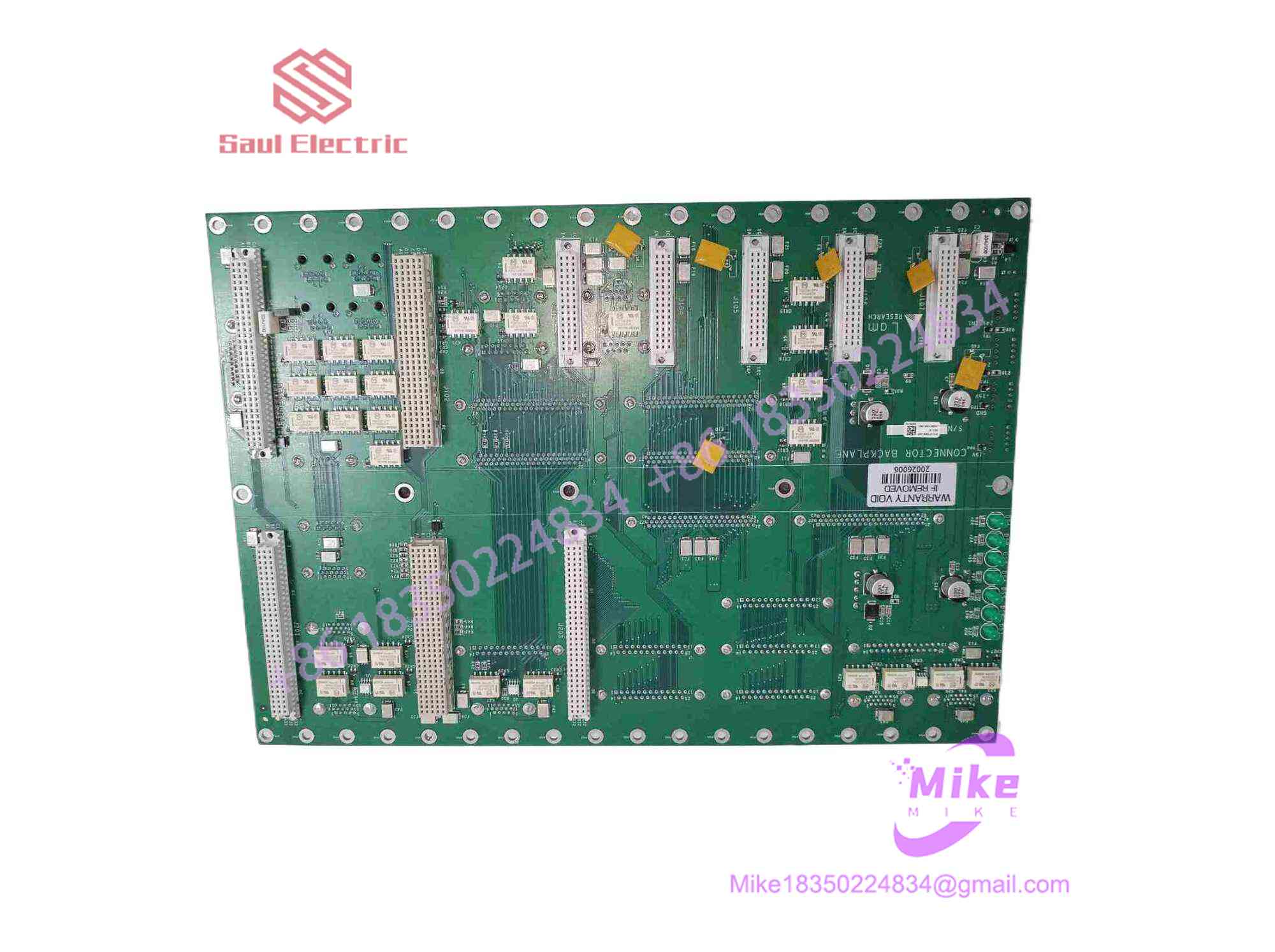
810-072906-005
Key Technical Specifications
| Parameter | Specification / Threshold |
| Part Number | 810-072906-005 |
| Board Type | Main System Backplane / Interconnect Distribution Board |
| OEM Manufacturer | Lam Research Corporation |
| Platform Support | Lam 2300, Kiyo, Alliance Plasma Systems |
| Interface Array | High-density Sub-D connectors (DB-9, DB-25), ribbon card sockets |
| Power Distribution | Multi-pin heavy-duty Molex headers for +24V, +5V, +3.3V, and ±15V rails |
| Card Slots | Multi-slot guide rails for drop-in daughterboard integration |
| PCB Layer Count | Multi-layer PCB with heavy copper trace planes & ground isolation |
| Operating Temp Range | 10°C to 50°C (Enclosure internal ambient rating) |
| Protective Finish | Industrial conformal coating for humidity and process gas resistance |
Global Sourcing & Live-Test SOP (Transparency Core)
Deploying a primary backplane module into a cleanroom production line leaves zero room for error. We validate every incoming 810-072906-005 through a four-tier testing protocol prior to stocking:
- Inbound Micro-Inspection & Trace Integrity:
- Full optical microscopic scan of all Sub-D solder joints, pin headers, and internal trace paths to detect micro-fissures or trace lifting.
- Verification of all backplane gold-plated contacts and edge sockets for pin deformation, bent pins, or thermal discoloration.
- Serial tracking and revision cross-referencing against OEM engineering change notices.
- Power Rail & Continuity Testing:
- High-pot and point-to-point resistance checks across power and ground planes to ensure zero internal layer shorts.
- Applying full operational DC voltages (+24V, +5V, ±15V) to power input headers under simulated amp loads to verify zero voltage drop across distribution traces.
- Rack Integration & Active Node Simulation:
- Seating a complete suite of functional test cards (Node controllers, LonWorks PIO boards) into the backplane slots inside a Lam test bench.
- Executing full multi-node data transmission over 24 hours in a 45°C environmental test chamber to confirm trace stability under thermal stress.
- Final Preparation & ESD Sealing:
- De-dusting and contact treatment on all Sub-D and ribbon interfaces using residue-free cleaner.
- Vacuum sealing in heavy-duty ESD conductive bags with integrated humidity indicators and fresh desiccant.
The Field Engineer’s Pitfall Guide
- ❗ Distorted Frame Mounting & PCB Stress:
Never force the 810-072906-005 into a warped or misaligned card cage frame. Because of its large surface area, tightening mounting screws out of sequence can flex the PCB, cracking hidden inner-layer vias—I’ve seen tech teams ruin a functional backplane simply by torquing corner screws down before all alignment pins were seated flush.
- ❗ Mating Connector Pin Crush during Harness Strain:
The front and top Sub-D connector arrays interface directly with heavy, rigid tool wiring harnesses. Pulling on these harnesses without proper strain relief brackets will peel solder pads right off the board or push internal socket pins out of alignment, causing intermittent channel drops during tool thermal cycling.
- ❗ Failure to Clear Shorted Downstream Cards:
If a shorted node board burned out your original backplane, plugging that same bad daughterboard into a fresh 810-072906-005 will instantly blow power distribution traces on the new board. Always resistance-test all sub-cards for power-to-ground shorts before inserting them into the newly installed backplane.
Intent-Driven FAQ
What are the signs that a Lam 810-072906-005 backplane needs replacement?
Typical indicators include multiple daughterboards losing power or communication simultaneously, visible charring around main power headers, or intermittent bus faults that shift when the card cage is physically tapped or flexed. If individual cards test good in another slot but fail in a specific position on the backplane, the backplane socket or trace path has failed.
Can I repair damaged traces on an 810-072906-005 in the field?
Field jumpering or trace soldering is strongly discouraged on semiconductor tool backplanes. Because this board routes high-speed data signals alongside high-current DC power rails, manual solder bridges can introduce impedance mismatches, noise pickup, or voltage drops that compromise tool safety interlocks.
Is the 810-072906-005 backward compatible with older revision backplanes?
Compatibility depends on the specific revision index of your card cage chassis and tool software release. While physical dimensions and connector layouts remain consistent across the 810-072906 series, trace routing changes between major DASH revisions can affect specific pin assignments. Always verify part number compatibility with your tool’s manual before swapping.
Does replacing the system backplane require software recalibration?
No. The backplane itself contains passive routing traces, connectors, and filtering networks without onboard programmable flash memory. However, after swapping the backplane, you must perform a complete tool diagnostic boot to ensure the host CPU successfully re-discovers all connected node cards and fieldbus devices.
What warranty coverage is provided for this refurbished backplane?
Every fully tested and certified surplus 810-072906-005 backplane board comes with a standard 1-year replacement warranty. If any distribution channel, connector socket, or power rail demonstrates hardware failure under normal operating parameters within 365 days of receipt, an advance replacement unit or repair service will be provided immediately.





