

Description
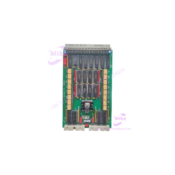
GESPAC GESOUT-3 OUT-3B | 32-Channel Digital Output Board
Product Introduction
When a legacy controller needs all 32 output points working again, the important number on the nameplate is not the board’s physical size—it is the 32-channel output architecture. The GESPAC GESOUT-3 OUT-3B is an industrial digital output card built around four 8-channel groups and open-collector transistor outputs. Available industrial records specify 100 mA output capability with 12 V, 24 V, or 48 V configurations.
The GESOUT-3 family is also documented as optically isolated. GESPAC training material identifies the GESOUT-3A/3B boards as providing 2500 V optical isolation, with 32 digital outputs. It describes the board-level outputs as active high and notes that the termination card can invert those signals to active low in a particular vehicle-control application.
That last detail is worth keeping in mind during a migration or replacement project: logical polarity at the controller board is not necessarily the same thing as the polarity seen by the field device. The termination hardware and host-system wiring are part of the actual signal path.
The GESOUT-3 OUT-3B is therefore best treated as a system-specific legacy output card rather than a generic modern PLC output module.
GESOUT-3 OUT-3B
Key Technical Specifications
- Manufacturer: GESPAC
- Model: GESOUT-3
- Variant: OUT-3B
- Functional Type: Digital output / industrial output board
- Number of Outputs: 32
- Port Organization: Four 8-channel output groups
- Output Technology: Open-collector transistor outputs
- Rated Output Current: 100 mA per output, according to available component records
- Supported Output Voltage: 12 V / 24 V / 48 V configurations
- Isolation: Optical isolation
- Isolation Rating: 2500 V for the GESOUT-3A/3B family according to GESPAC training documentation
- Logic Behavior: Active high at the GESOUT board level
- Application: Industrial machine and process-control output interface
- Lifecycle: Legacy/discontinued
The GESPAC family includes both GESOUT-3A and GESOUT-3B variants. A current industrial parts catalog identifies GESOUT-3A as a 32-channel industrial output board with open-collector outputs, while separate component records identify GESOUT-3B as a 32-output industrial module with 100 mA outputs and 12/24/48 V configurations.
Output Architecture
The four 8-channel arrangement is useful when troubleshooting because a failure affecting one group of eight outputs may point toward the port, termination interface, or associated power circuitry rather than 32 independent field-device failures.
The open-collector architecture also means the external circuit must be evaluated correctly. Do not treat these outputs as if they were conventional sourcing outputs from a modern PLC. Verify the load return path, external supply arrangement, output voltage configuration, and termination hardware before energizing a field circuit.
Global Sourcing & Live-Test SOP
1. Inbound Verification
For an obsolete GESOUT-3 OUT-3B, start with identification rather than power-up.
Record:
- GESPAC manufacturer marking
- model marking
- OUT-3B variant
- PCB revision
- Serial number or assembly number
- Date codes
- Connector condition
- Terminal/termination interface
- Visible jumpers or configuration links
- Signs of previous repair
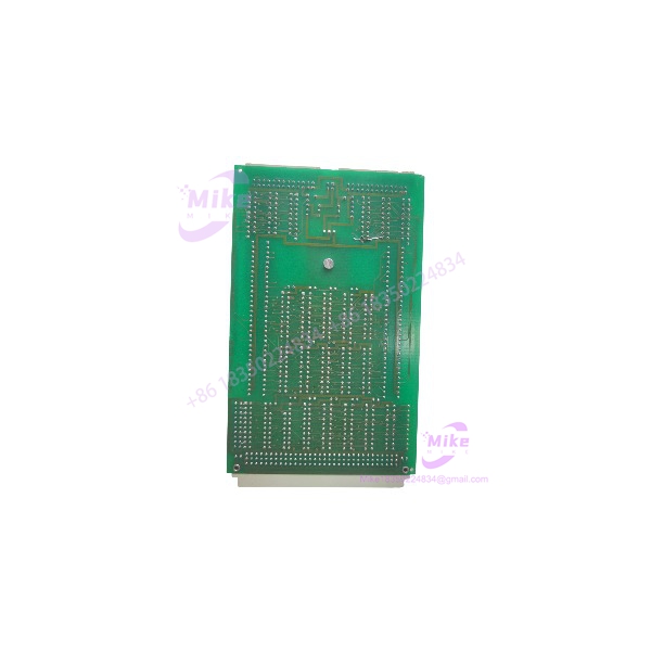
Photograph both sides of the board and retain clear images of all labels.
The marketplace listing for this particular item identifies it as a used GESPAC /OUT-3B PCB and states that the supplied unit corresponds to the photographs. That makes the actual board population and physical condition particularly important during procurement.
2. Visual and Electrical Inspection
Before insertion into the controller:
- Inspect the PCB for cracked components or damaged solder joints.
- Check the edge connector for oxidation or mechanical damage.
- Inspect output-driver components for discoloration.
- Check isolation components for physical damage.
- Inspect termination connectors.
- Verify that configuration links match the known-good board.
- Check for contamination, corrosion, and evidence of liquid exposure.
Do not apply field voltage merely to determine whether the card is alive. Establish the correct output wiring first.
3. Controlled Functional Test
Use a compatible GESPAC rack/controller and an appropriate test load.
A useful sequence is:
- Install the board with system power removed.
- Verify the board position and keying.
- Power the controller.
- Confirm the CPU recognizes the output board where system diagnostics provide that information.
- Exercise each output group individually.
- Verify the expected logic state.
- Measure the output behavior with a suitable meter or oscilloscope.
- Test representative loads.
- Repeat the test across all 32 points.
For transistor outputs, a test load should be chosen to stay comfortably inside the documented current limit. Do not use a large solenoid or contactor coil as a first-pass test.
4. Load Simulation
A programmable DC load or appropriately rated resistive/inductive test fixture is preferable to connecting production actuators during initial verification.
For inductive loads, confirm that the termination and suppression arrangement is correct. Switching an inductive load without appropriate suppression can produce voltage transients that stress the output transistor and isolation circuitry.
Record:
- Commanded state
- Measured output voltage
- Load current
- Output leakage when OFF
- Switching behavior
- Channel-to-channel consistency
A Fluke multimeter is adequate for basic DC voltage/current verification. Use an oscilloscope when investigating switching transients, abnormal turn-off behavior, or intermittent output faults.
5. Extended Run
For critical spare inventory, operate the card through repeated output cycles.
A practical acceptance test can include:
- Sequential channel activation
- Group-by-group cycling
- Simultaneous representative loading
- Repeated controller restarts
- Extended powered operation
- Thermal inspection after sustained activity
If one output fails only after repeated switching, do not classify the board as fully operational simply because static continuity testing passed.
Field Engineer’s Pitfall Guide
❗ Warning 1 — Open Collector Is Not the Same as a Sourcing Output
The uses open-collector digital outputs. That architecture requires the external circuit to be wired correctly.
Do not connect a field load based solely on the assumption that a modern PLC’s sourcing-output wiring applies. Verify the load supply, return path, termination card, and output voltage arrangement first.
❗ Warning 2 — 32 Outputs Does Not Mean 32 Identical Independent Circuits
The board is organized as four 8-channel groups. A fault affecting eight consecutive points deserves a different diagnostic approach from a single failed transistor.
Start with the shared port circuitry, connector, termination interface, and associated supply before replacing individual field devices.
❗ Warning 3 — Check the System-Level Signal Polarity
GESPAC documentation describes the board outputs as active high, but also documents a vehicle application in which termination-card transistors invert those signals to active low.
That means the correct logic state must be verified at the actual field interface—not inferred from the board designation alone. This becomes particularly important when replacing a termination assembly or changing the migration strategy.
Intent-Driven FAQ
What is the GESPAC ?
The GESPAC is a 32-channel industrial digital output board. Available records identify it as an open-collector output module with four 8-channel groups.
How many outputs does the have?
The family provides 32 digital outputs. GESPAC training documentation confirms the 32-output architecture for the GESOUT-3A/3B family.
What type of outputs does the use?
Available component records identify the outputs as open collector, with a documented 100 mA output rating. The same records identify 12 V, 24 V, and 48 V output configurations.
Is the optically isolated?
Yes. GESPAC training documentation identifies optical isolation for the GESOUT-3A/3B family and specifies 2500 V isolation.
Is an analog output module?
No. Despite some marketplace descriptions incorrectly categorizing it as an analog I/O product, the stronger technical evidence identifies the /3B as a 32-channel digital output board.
Can I replace the with any 32-channel PLC output card?
No. Channel count alone is insufficient. Check output topology, voltage, current, isolation, connector pinout, termination hardware, logic polarity, rack/backplane compatibility, and the host controller’s I/O addressing before substitution.
Is the still a current product?
Available industrial-control catalogs classify GESPAC output boards such as the GESOUT-3B as discontinued/legacy equipment.
For this type of obsolete hardware, a tested surplus board can be useful as a maintenance spare—but the exact PCB revision and termination arrangement should be documented before it enters production inventory.





