


Description
FANUC A660-2006-T324L | Teach Pendant Cable, New Surplus
Architect’s Product Breakdown
The FANUC A660-2006-T324L cable functions as the critical communication lifeline bridging the operator and the robotic controller. Designed to withstand continuous flexing, mechanical stress, and harsh factory environments, this cable houses robust internal shielding to protect sensitive data and emergency-stop safety lines from high-frequency electromagnetic interference (EMI) generated by nearby servo drives and welding equipment.
Deploying or replacing a teach pendant cable requires meticulous routing through cable tracks or drop arms to prevent pinching, sharp radius bends, or crushing under cell doors. When installing a replacement run, technicians must ensure that connector backshells are securely tightened and moisture seals are intact. A compromised outer jacket or loose connector pin can introduce intermittent E-stop faults, communication drops, or erratic pendant behavior that halts production lines.
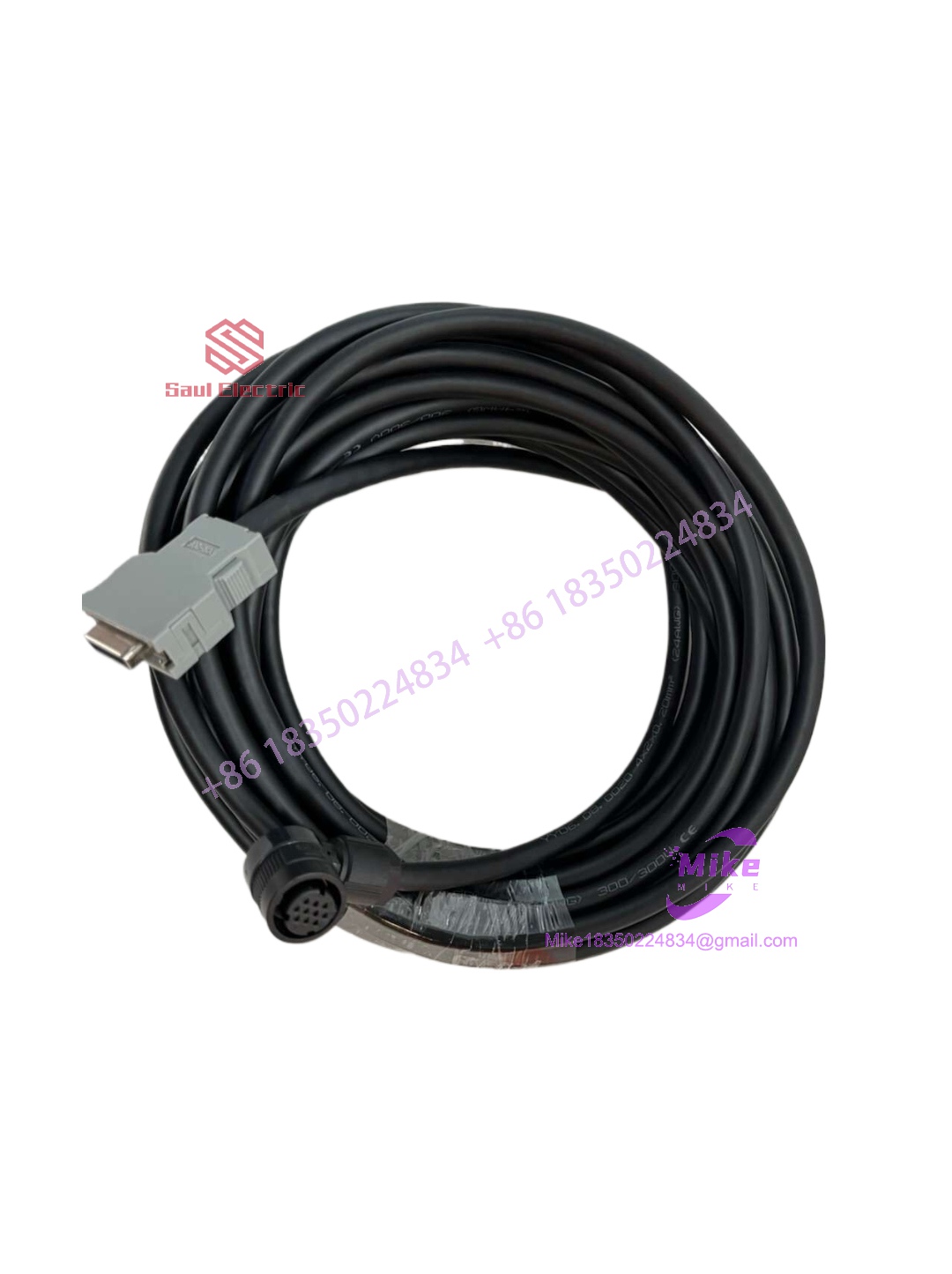
A660-2006-T324L
Key Technical Specifications
| Parameter | Specification |
| Manufacturer | FANUC |
| Part Number Root | A660-2006-T324L (Variants include specific length options like #L=22M) |
| Component Category | Robot Teach Pendant / Operator Interface Cable |
| Compatible Controller Series | FANUC R-30iA, R-30iB, and related industrial robot cabinets |
| Jacket Material | Oil-Resistant, Heavy-Duty Industrial Elastomer |
| Shielding | Dual-Layer Braided Shield / Foil Protection against EMI |
| Cooling Method | Natural Convection / Ambient Air |
| Operating Temperature | 0°C to 45°C (Standard Factory Floor Limits) |
Field Engineer’s Pitfall Guide
- Ignoring Minimum Bend Radius Limits: Warning: Tying or routing the cable around sharp structural corners or forcing tight radius bends breaks internal copper strands over time. Always adhere to manufacturer bend-radius specifications, especially inside dynamic articulating cable tracks.
- Strain Relief Neglect: Do not let the entire weight of the cable hang unsupported from the teach pendant or controller bulkhead. Failing to anchor the strain relief grips properly puts direct pulling tension on the delicate internal solder joints and connector pins.
- Hot-Plugging the Controller Port: Never plug or unplug the teach pendant cable while the main controller power is switched on. Doing so risks electrical arcing across pins, communication bus corruption, and potential damage to internal interface boards. Always execute a complete system shutdown or follow proper disconnect protocols.
QA & Testing SOP (Transparency)
- Visual & Mechanical Audit: Incoming cables are inspected across their entire length for jacket abrasions, cuts, crushing marks, and connector pin corrosion or bending.
- Continuity & Pinout Verification: Technicians utilize automated diagnostic test rigs to verify 1:1 pin continuity, shield grounding integrity, and isolation resistance across every conductor.
- Flex & Stress Simulation: Critical node connections undergo mechanical stress testing to ensure the molding and strain relief boots withstand repetitive manipulation.
- Environmental & Packaging Seal: Approved cables are cleaned, capped with protective dust covers, and sealed in anti-static moisture-barrier packaging prior to inventory stocking.
Technical FAQ
Can the length of the A660-2006-T324L cable be extended using generic field couplers?
No. Splicing or using unapproved third-party extension couplers degrades signal integrity, disrupts critical emergency-stop safety loops, and introduces severe noise vulnerability across the serial data lines. Always use a single, correctly rated continuous cable length.
What causes a “Teach Pendant Disconnected” alarm immediately after swapping the cable?
This usually points to an unseated connector latch, bent pins inside the plug housing, or a mismatch in the cable wiring configuration (e.g., USB vs. non-USB variants). Inspect the plug alignment carefully.
Are the connector ends field-repairable if a pin breaks?
Due to the high-density pin layout, internal shielding requirements, and safety-critical nature of emergency stop circuits, field-splicing or manual pin replacement is strongly discouraged. Full cable assembly replacement ensures absolute reliability and safety compliance.





