

Description
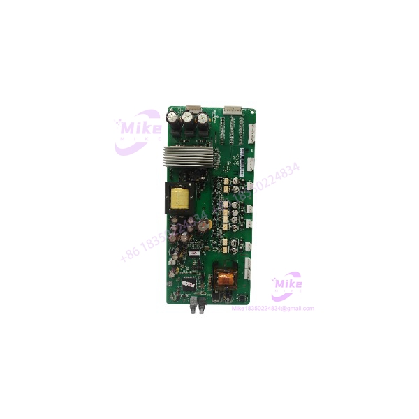
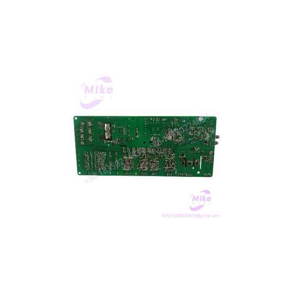
Emerson MFM600N0P1 | Fiber-Optic Control Board
Product Introduction
The Emerson MFM600N0P1 is a control and signal circuit board used within Emerson high-voltage drive equipment. Available component documentation identifies the MFM600N0P1 specifically as a fiber-optic control and signal board, separating it from the power-stage and other control boards used in the same drive architecture.
For maintenance procurement, the MFM600N0P1 should therefore be treated as a system-specific electronic assembly rather than a generic communications card. The exact drive platform, PCB revision, connector arrangement, firmware relationship, and fiber-optic interface configuration should be matched before installing a replacement. A third-party component listing also associates this part number with Fuji high-voltage inverter equipment marketed as an Emerson drive, but that association should be confirmed against the installed drive nameplate and board markings.
MFM600N0P1
Key Technical Specifications
- Model: MFM600N0P1
- Manufacturer/Brand: Emerson
- Assembly Type: Control and signal circuit board
- Board Function: Fiber-optic control and signal interface
- System Type: High-voltage inverter/drive system
- Signal Medium: Fiber optic
- Part Number: MFM600N0P1
- Board Family: MFM600
- Application: High-voltage drive control electronics
- PCB Revision: Verify from physical board label
- Connector Configuration: Verify against the installed board
- Firmware/Configuration Dependency: Verify against the host drive
- Condition: Legacy / Verify condition
Specification note: Publicly indexed documentation for this exact board is limited. I have deliberately not assigned unsupported voltage, current, fiber-channel count, optical wavelength, communication protocol, dimensions, or environmental ratings to the .
Application Scenarios & Pain Points
1. High-Voltage Drive Board Replacement
The is relevant when a high-voltage drive develops a control or fiber-optic signaling fault while the remaining drive hardware is still serviceable.
Replacing the affected board can be materially different from replacing the complete drive assembly, but only when the replacement PCB matches the original hardware revision and system configuration.
2. Fiber-Optic Control Signal Faults
A drive may exhibit communication, gating, control, or diagnostic abnormalities even when the main power-stage components test correctly.
The should be investigated alongside:
- Fiber-optic transmit/receive paths
- Connector condition
- Host control electronics
- Board revision
- Drive diagnostics
- Power supply rails
- Associated interface boards
3. Obsolete High-Voltage Drive Maintenance
For legacy Emerson/Fuji drive installations, locating an exact replacement PCB can be more practical than redesigning the complete drive control architecture.
The critical procurement requirement is exact board identity, not simply an MFM600-series part number.
4. Repair-Shop Board-Level Testing
The can also be handled as a controlled repair-shop assembly where the board is inspected, powered through an appropriate test fixture, and evaluated with the matching drive-side interfaces.
Do not apply arbitrary bench power to an unidentified connector: the board’s internal power requirements should be established from the applicable Emerson drive documentation or the original assembly.
QA & Live Testing SOP
For a used or surplus , inspection should be performed against the original drive configuration whenever possible.
- OEM and Board Identity
- Confirm the marking on the PCB or label.
- Record board revision, serial information, and date codes.
- Photograph both sides of the PCB before testing.
- Physical Inspection
- Inspect PCB traces, components, connectors, fiber-optic interfaces, and mounting hardware.
- Look for corrosion, contamination, cracked solder joints, burned components, and previous repair work.
- Check fiber-optic connectors for contamination or physical damage.
- Drive Compatibility Verification
- Record the host drive manufacturer and exact model.
- Compare the installed board with the replacement board.
- Verify connector locations and board revision.
- Confirm that the replacement is intended for the same drive architecture.
- Fiber-Optic Inspection
- Inspect transmit and receive fiber connections.
- Use appropriate optical cleaning procedures.
- Verify correct fiber routing and channel identification.
- Do not bend or sharply kink fiber-optic cables during testing.
- Controlled Electrical Test
- Test only with the appropriate board-level fixture or compatible host drive.
- Verify required low-voltage supply rails according to the applicable system documentation.
- Monitor for abnormal current consumption or localized heating.
- Functional Drive Test
- Install the board into a controlled test system where available.
- Verify drive initialization and diagnostic status.
- Check fiber-optic signaling under controlled operating conditions.
- Confirm that the drive reaches its normal control state before any high-voltage operation.
- ESD-Safe Packaging
- Handle the PCB using ESD controls.
- Place the board in an antistatic bag.
- Protect fiber-optic connectors from dust and mechanical impact.
- Use rigid packaging to prevent PCB flex during shipment.
Field Engineer’s Pitfall Guide
❗ Do not confuse with a Micro Motion flowmeter. Search results for the same string can produce an unrelated Emerson MFM600 flow-measurement result. The evidence relevant to this industrial automation part identifies as a fiber-optic control/signal board.
❗ Do not substitute an MFM600-series board solely because the prefix matches. Related boards can perform different functions. For example, component inventory data separately identifies MFM075N0P5 as a power/protection board and MFM050N0P4 as a capacitor board, demonstrating that the MFM designation alone does not establish interchangeability.
❗ Verify the PCB revision. A physically similar replacement can still have different component populations, connector assignments, or control-system compatibility.
❗ Treat fiber-optic connectors as precision interfaces. Dirt, damaged ferrules, incorrect transmit/receive routing, or excessive cable bending can produce symptoms that resemble a defective control board.
❗ Do not perform a live high-voltage test as the initial acceptance test. Establish board identity, inspect the PCB, verify low-voltage behavior, and confirm fiber signaling before energizing the associated high-voltage power stage.
❗ Do not assume the public specifications are complete. Exact electrical ratings and interface details were not sufficiently documented in the sources reviewed. Obtain the applicable drive manual or board-level documentation before specifying replacement voltage, current, optical parameters, or connector pinouts.
Intent-Driven FAQ
What is the Emerson ?
The is identified in available component documentation as an Emerson fiber-optic control and signal board for high-voltage drive equipment.
Is a Micro Motion flowmeter?
The exact string appears in some third-party search results as an alleged Micro Motion MFM600 flowmeter, but that conflicts with component inventory evidence identifying as an Emerson fiber-optic control/signal board. For industrial automation procurement, the physical board marking and host-drive application should determine the identity.
What type of equipment uses ?
Available evidence associates the board with high-voltage inverter/drive equipment, including an aftermarket listing connecting with Fuji high-voltage inverter equipment marketed as an Emerson drive. Verify the exact host-drive model before purchasing.
What does the board do?
It is identified as a fiber-optic control and signal board, meaning its role is associated with control/signaling through optical interfaces within the drive system.
Can be tested by itself?
Not safely without establishing the board’s required power rails, connector pinout, and test procedure. A controlled test fixture or the correct host drive is preferable to applying arbitrary bench power.
What should I verify before buying a used ?
Verify the marking, PCB revision, host drive model, connector configuration, fiber-optic interface arrangement, physical condition, and available test evidence. If possible, obtain photographs of the actual PCB label and both connector sides.
Is interchangeable with another MFM600 board?
Do not assume interchangeability. The available inventory evidence shows that other MFM-series boards perform different functions, including power/protection and capacitor functions. The exact order number and board revision should be matched.
What condition should be stated for a surplus ?
Unless actual inspection data is available, use “Legacy / Verify condition” rather than claiming tested, refurbished, new, or fully functional status.





