


Description
DEIF 11-0018905 | Aggreko Power Generator Controller
Dynamic Product Introduction
Tying multiple mobile diesel generators into a temporary plant grid without precise phase synchronization will instantly trip main air circuit breakers or explode transfer switches. When generator controllers experience frequency drift or internal relay contacts weld shut under high vibration, fleet reliability collapses. The DEIF/Aggreko 11-0018905 addresses this exact vulnerability, serving as a heavy-duty control and protection module designed specifically for critical temporary power and industrial microgrid installations.
Honestly, swapping out a failed genset controller with an uncalibrated third-party board is a gamble that risks severe engine hunting or reverse power tripping. Custom-engineered for Aggreko mobile power systems by DEIF, the 11-0018905 incorporates ruggedized anti-vibration circuitry and wide-temperature components to withstand harsh field environments. Dropping a verified unit into your genset control panel restores clean load-sharing handshakes, preventing voltage sag and engine stalls across demanding industrial site loads.
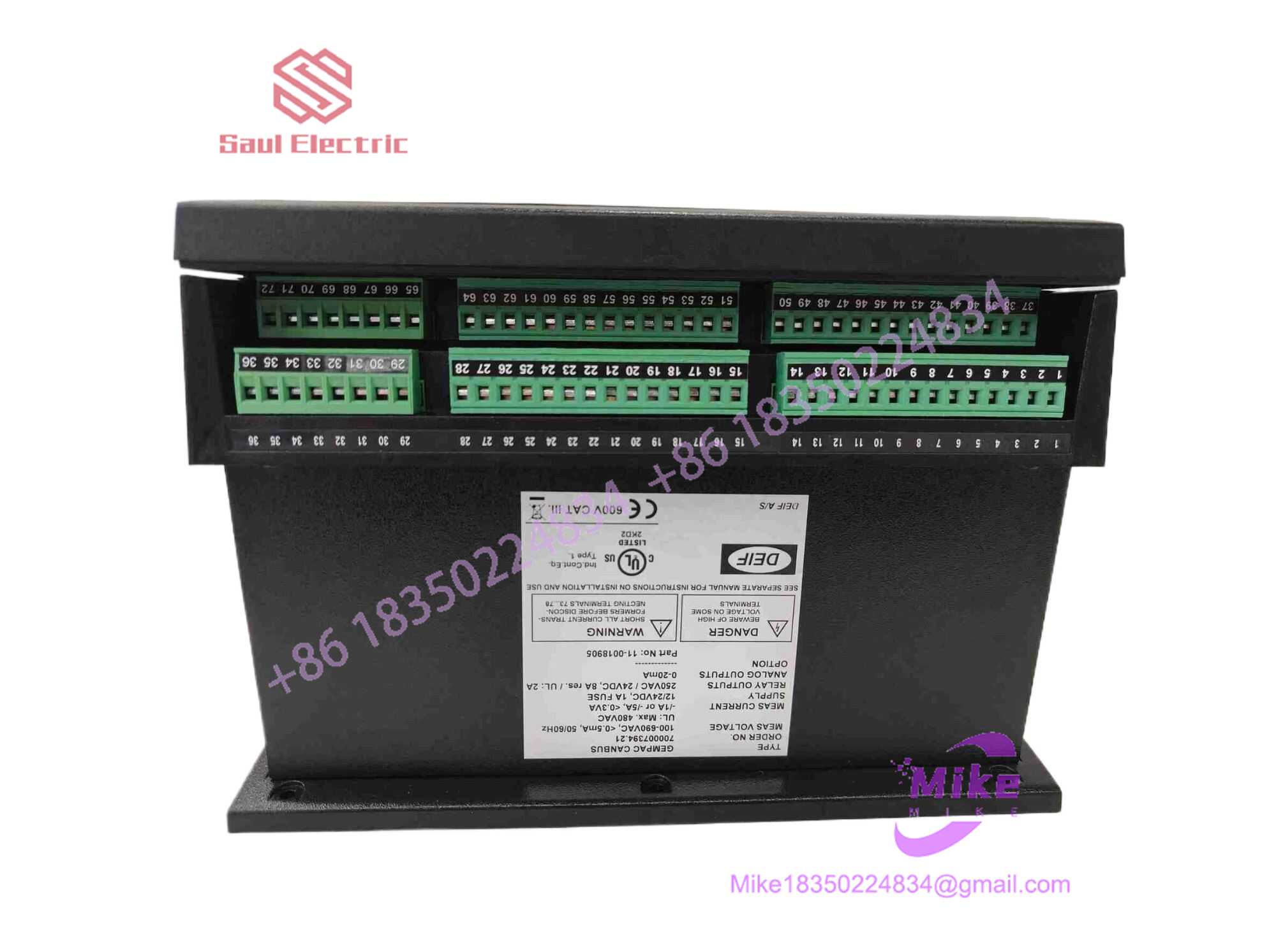
11-0018905
Key Technical Specifications
| Parameter | Specification Details |
| Model Part Number | 11-0018905 |
| Manufacturer / Partner | DEIF / Aggreko OEM Custom |
| Product Category | Generator Protection & Paralleling Controller |
| Control Functions | Auto Start/Stop, Phase Synchronization, Active/Reactive Load Sharing |
| Input Supply Voltage | 8V DC to 36V DC continuous (24V DC nominal) |
| Voltage Sensing Range | 100V AC to 480V AC (True RMS phase-to-phase) |
| Frequency Sensing Range | 30 Hz to 70 Hz (Precision \pm 0.1 Hz) |
| Communication Bus | Dual CANbus (Engine ECU / Load Share) & RS485 Modbus RTU |
| Protective Triggers | Over/Under Voltage, Over/Under Frequency, Reverse Power, Overcurrent |
| Operating Temperature | -40°C to +70°C (-40°F to 158°F) |
| Enclosure Rating | IP65 Front Panel (when gasket-mounted) |
Global Sourcing & Live-Test SOP (Transparency Core)
Surplus and replacement generator control hardware must undergo strict bench-testing before deployment to remote oilfield or utility backup sites. Every DEIF 11-0018905 module passing through our testing facilities is subjected to a four-tier quality control protocol.
Inbound Verification & Physical Auditing
Upon arrival, technicians verify firmware revision labels against OEM release notes and inspect all terminal blocks, optical displays, and housing seals for cracks or moisture ingress.
24V Logic & Signal Simulation
The module mounts directly into a automated test jig equipped with variable AC signal generators:
- Voltage/Frequency Ramping: 3-phase AC voltage and frequency signals are varied from 80% to 120% of nominal rating to verify trigger response times for over/under-voltage alarms.
- Current Loop Emulation: Secondary current transformer (CT) input channels receive 0–5A injections to verify accurate power factor and kW calculations.
+---------------------+     +-----------------------+     +--------------------------+
| Precision 3-Phase   | --> | DEIF 11-0018905       | --> | Digital Oscilloscope &   |
| AC Signal Generator |     | Controller Test Bench |     | CANbus Protocol Analyzer |
+---------------------+     +-----------------------+     +--------------------------+
Communication & Synchronizer Handshake Validation
Technicians hook the module to a dual-genset simulator network. The CANbus port is monitored using a protocol analyzer to verify error-free load-sharing data packets, while the analog governor/AVR speed bias outputs undergo line-smooth testing.
Thermal Burn-In & Safe Packaging
Passing units endure a continuous 12-hour thermal soak under full logic power. Once cleared, parameter sets are reset to factory defaults, terminal screws are checked, and the unit is wrapped in ESD barrier film inside high-density foam shipping boxes.
The Field Engineer’s Pitfall Guide
❗ Warning 1: CANbus Terminal Resistor Oversight
Never wire a replacement 11-0018905 into a multi-generator load-sharing network without checking internal or external DIP-switch termination resistors (120 \Omega). If the controller sits at either physical end of the CAN bus line and lacks proper termination, signal reflections will cause communication timeouts, resulting in sudden load-rejection or generator hunting under heavy site loads.
❗ Warning 2: Governor / AVR Analog Bias Voltage Polarity Mismatch
Connecting the speed governor or automatic voltage regulator (AVR) control bias outputs with reversed polarity will drive the engine to maximum overspeed or total voltage collapse during synchronization. Always verify whether your specific engine governor card requires a \pm 2.5 V DC, 0–10 V DC, or PWM adjustment signal before closing the breaker output line—I’ve seen site techs blow main generator fuses because they failed to check output bias jumper settings.
❗ Warning 3: Incorrect Current Transformer (CT) Phase Alignment
Wiring phase A current transformer signals into the phase B or C measurement terminals cocks the internal active power calculation. While the controller will still register AC voltage, the reverse power and kW load-share logic will miscalculate, causing the module to trip the breaker immediately upon parallel tie-in. Always perform a phase rotation check with a digital phase meter before closing main contactors.
Intent-Driven FAQ
Will swapping out the 11-0018905 clear custom engine setup parameters?
Yes. Engine parameters, CT ratios, breaker timing settings, and load-sharing PID gains are stored directly in non-volatile flash memory inside the module. Always export or manually document parameter files via the configuration software or front screen before pulling a failed card.
Can I use the DEIF 11-0018905 on standard non-Aggreko generator sets?
While the hardware base is manufactured by DEIF, the 11-0018905 model number often carries Aggreko-specific firmware maps and connector pinouts. It works directly in Aggreko rental fleets and compatible DEIF-based paralleling systems; using it in generic panels may require matching the controller’s exact firmware profile.
What is the most common field failure mode for these genset modules?
Transients and voltage spikes coming off a dying 24V starter battery during engine cranking cause the majority of field failures. Over time, severe voltage drops below 8V DC can corrupt operational memory or damage the internal power supply regulation circuit.
Is it safe to flash or update firmware directly on the test bench?
Only if you use a stabilized, isolated 24V DC power supply and an official DEIF interface cable. Interrupting power or losing communication mid-flash will brick the controller’s bootloader, requiring factory-level chip reprogramming.
How do I verify whether a synchronization fault is caused by the 11-0018905 or the main circuit breaker?
Check the controller display status during the paralleling sequence. If the 11-0018905 successfully aligns the synchroscope (phase angle, frequency, and voltage match) and issues a breaker close command signal, but the breaker fails to latch, the fault lies in the breaker trip coil, auxiliary contacts, or interconnecting relay wiring.





