

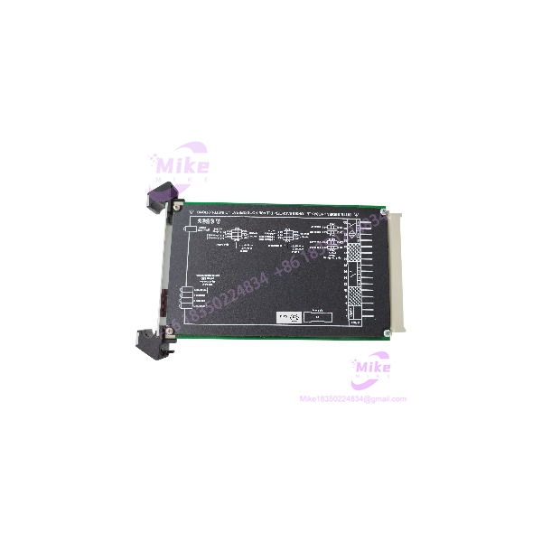
Description
COOPER GHG122 | CEAG 2/942 Industrial Switch Amplifier
Product Introduction
The COOPER GHG122 is not simply a generic terminal block despite some surplus-market descriptions. The documented GHG122 catalog family is associated with the CEAG 2/942 switch amplifier, an interface designed to transfer switching information between hazardous-area field devices and the control system. Cooper Crouse-Hinds documentation identifies versions with NAMUR inputs, galvanic isolation, relay outputs, and hazardous-area approvals.
The critical procurement issue is the complete GHG122 catalog number. The family includes different channel counts and supply voltages. For example, Cooper documentation lists GHG 122 3111 D 1003 as a one-channel, 120 VAC version and GHG 122 3121 D 1003 as a two-channel, 120 VAC version. It also lists 230 VAC and 24 VDC variants.
That means GHG122 alone should not be treated as a complete electrical specification. For a production replacement, match the full suffix printed on the device or nameplate.
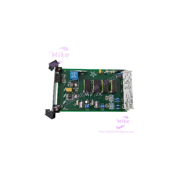
GHG122
Key Technical Specifications
- Manufacturer: Cooper Crouse-Hinds / CEAG
- Family: GHG 122
- Associated Series: 2/942
- Function: Switch signal amplification/interface
- Input Type: NAMUR specification and mechanical contacts documented
- Input Channels: 1 or 2, depending on suffix
- Output: 1 changeover relay per channel
- Output Voltage Rating: Up to 250 VAC / 100 VDC
- Output Current Rating: Up to 5 A AC / 2 A DC
- Output Power Rating: 100 VA / 50 W
- Galvanic Isolation: Yes
- Power Supply Options: 120 VAC, 230 VAC, and 24 VDC variants
- Phase Reversal: Via front switch on documented versions
- Operating Temperature: -20°C to +60°C in the referenced CEAG 2/942 documentation
- Relative Humidity: Less than 75% average; up to 95% provided the unit is kept dry
- Mounting: DIN-rail mounted versions documented
- Hazardous-Area Interface: EEx ia/ib versions documented
- Line Monitoring: Documented for the 2/942 family
The exact ratings above apply to the documented 2/942/GHG122 family; verify the complete suffix before applying them to a particular unit.
Global Sourcing & Live-Test SOP
A surplus should be tested as a hazardous-area interface component, with particular attention to its exact suffix and power configuration.
1. Inbound Verification
- Photograph the complete nameplate.
- Record the entire catalog number after , not just the family designation.
- Confirm channel count.
- Confirm supply voltage.
- Identify the hazardous-area certification marking.
- Inspect terminal blocks for corrosion or damaged insulation.
- Check the enclosure and DIN-rail mounting mechanism.
- Inspect adjustment switches and front controls.
- Record manufacturing information and serial number where available.
2. Electrical Verification
Before energizing:
- Compare the nameplate supply with the intended test voltage.
- Verify terminal identification against the correct wiring diagram.
- Check for short circuits between supply, input, output, and ground terminals.
- Inspect relay contacts for contamination or mechanical damage.
- Verify continuity with power removed where appropriate.
Do not apply 120 VAC, 230 VAC, or 24 VDC merely because another variant uses that voltage.
3. Functional Simulation
For a suitable test setup:
- Apply the specified supply voltage.
- Simulate the appropriate NAMUR input or approved contact input.
- Monitor the relay output.
- Test both channels on a two-channel version.
- Verify switching behavior at repeated input transitions.
- Check line-monitoring behavior where supported.
- Confirm the relay returns to the expected state when the input condition is removed.
For field wiring verification, a calibrated meter can confirm the expected input/output states, but hazardous-area testing must follow the applicable installation and test procedures.
4. Extended Test
Run repeated switching cycles while monitoring:
- Relay operation
- Input recognition
- Output contact stability
- Supply behavior
- Abnormal heating
- Intermittent channel faults
- Mechanical switch operation
Record the exact tested suffix, supply voltage, channel count, and test conditions.
5. Final Preparation
For a tested replacement:
- Record complete catalog number.
- Photograph nameplate and terminal layout.
- Record supply voltage.
- Record channel configuration.
- Preserve original terminal labeling.
- Protect terminals against impact and contamination.
- Package the unit appropriately for industrial electronics.
- Include the tested configuration with the shipment documentation.
Field Engineer’s Pitfall Guide
❗ is a family designation, not a complete replacement specification
This is the biggest sourcing trap. Cooper documentation shows multiple variants with different channel counts and supply voltages. A and a , for example, are not interchangeable merely because both begin with .
❗ Do not substitute supply voltage
The documented family includes 120 VAC, 230 VAC, and 24 VDC versions. Confirm the full suffix and nameplate before energizing the replacement. A visually identical CEAG interface with a different power variant can be electrically incompatible.
❗ Preserve hazardous-area certification requirements
The 2/942 documentation identifies EEx ia/ib protection and NAMUR applications. The certification is part of the system design, not simply a label on the module. If the is being used in a classified area, match the actual approval, field-device type, barrier/interface arrangement, and installation requirements rather than substituting a conventional signal relay.
Intent-Driven FAQ
What is the COOPER ?
The is part of Cooper Crouse-Hinds / CEAG’s GHG 122 family associated with the 2/942 switch amplifier. It provides an interface between field switching devices and control-system circuits.
Is the a PLC I/O module?
No. It is better classified as a signal interface / switch amplifier rather than a conventional PLC digital input or output module.
What type of inputs does it accept?
The documented 2/942 family supports NAMUR inputs and mechanical contacts, with line monitoring specified for the family.
How many channels does the have?
That depends on the suffix. Cooper documentation lists both one-channel and two-channel versions. Do not infer channel count from the family name alone.
What output does the provide?
The documented 2/942 version uses a relay changeover output. Published ratings for the family include up to 250 VAC/100 VDC, 5 A AC/2 A DC, and 100 VA/50 W. Verify the exact installed variant before using these limits in a production circuit.
What power supply does the require?
There is no single answer for the entire family. Documented variants include 120 VAC, 230 VAC, and 24 VDC supply versions. The full catalog suffix must be matched before commissioning.
Is the suitable for hazardous-area systems?
Documented CEAG 2/942 versions are designed for hazardous-area interface applications and include EEx ia/ib protection. The actual certification and permitted installation arrangement must be verified from the complete catalog number and applicable site requirements.





