


Description
Bristol Babcock 396352-01-4 Card | ControlWave Process I/O Module
Architect’s Product Breakdown
The Emerson / Bristol Babcock 396352-01-4 operates as a high-density analog input module within the ControlWave architecture. Deployed extensively in remote telemetry units (RTUs) and hybrid process controllers, this card processes field-derived 4-20 mA instrumentation loops—such as pressure transmitters, flow meters, and level sensors—translating physical process variables into high-precision digital data streams for the backplane processor.
Integration requires careful verification of field loop power and signal terminal assignments on the matching local terminal assembly. Because these modules often reside in remote, harsh environments subject to electrical noise, proper shielding and cabinet ground bonding are non-negotiable. Engineers must configure channel scaling ranges via ControlWave Designer software to match process span requirements precisely, ensuring accurate data handoffs across the internal serial communication bus.
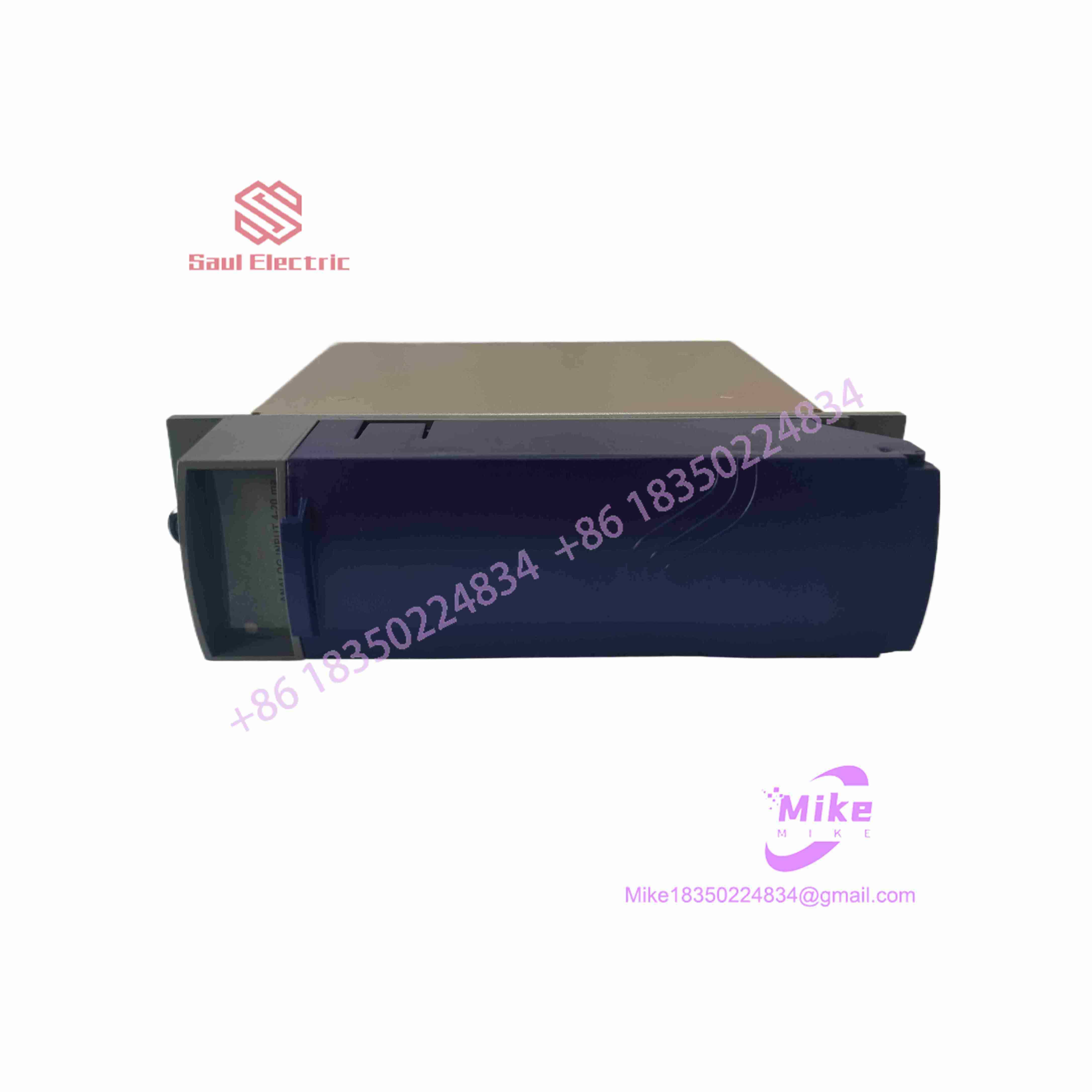
396352-01-4
4. Key Technical Specifications
| Parameter | Specification Data |
| Module Type | 16-Channel Analog Input Module |
| Input Signal Range | 4-20 mA DC current loops |
| Input Points | 16 single-ended / differential points (Series C) |
| Hardware Revision | Series C (-01-4 configuration variant) |
| Isolation | Channel-to-bus and channel-to-channel isolation features |
| Operating Temperature | -40^\circC to +70^\circC |
| Storage Temperature | -40^\circC to +85^\circC |
| Relative Humidity | 5% to 95% non-condensing |
| Enclosure Type | Plug-in module for ControlWave chassis backplane |
Field Engineer’s Pitfall Guide
- Common-Mode Voltage Exceedance: Tying unisolated loop grounds across different external power supplies can introduce common-mode voltage spikes that saturate input channels or damage internal ADC components. Verify loop isolation schemas before landing wires.
- Series Revision Incompatibilities: Replacing an older hardware revision card with a Series C (-01-4) variant without verifying the underlying ControlWave firmware version can trigger persistent configuration mismatch faults on the controller.
- Open-Loop Fault Misinterpretation: I have seen instrumentation techs troubleshoot phantom low-limit process alarms only to find that a field loop fuse blew due to an un-fused auxiliary power tap. Always verify loop supply voltage at the terminal block before pulling the module.
QA & Testing SOP (Transparency)
- Visual & Origin Inspection: Verification of OEM manufacturing labels, Series C stamps, connector pins, and conformal coating integrity.
- Bench Test Environment: Insertion into a live ControlWave test rack powered by validated system supplies.
- Diagnostic Handshake: Firmware verification, backplane communication bus health checks, and module status LED validation.
- Current Simulation Test: Injection of calibrated 4 to 20 mA precision current steps across all 16 input points to verify analog-to-digital conversion accuracy.
- Packaging: ESD-shielded anti-static packaging encased in high-density anti-shock foam.
Technical FAQ
- Can I hot-swap this analog input module while the system is powered? System design guidelines vary by exact housing enclosure; however, standard safe practice for ControlWave hardware mandates powering down the local rack segment before card replacement to prevent backplane bus latch-up.
- What does the “-01-4” suffix designate? It identifies the specific hardware configuration, channel density, and firmware packaging variant assigned by Bristol Babcock / Emerson.
- Does the module retain calibration data after power loss? Yes, calibration and configuration parameters are stored in non-volatile onboard memory, requiring no local backup batteries.
- What causes input channels to freeze at maximum scale? Channels pegging at maximum scale typically indicate an open sensor loop, a missing loop power supply, or a damaged input protection diode caused by an upstream lightning surge.





