

Description
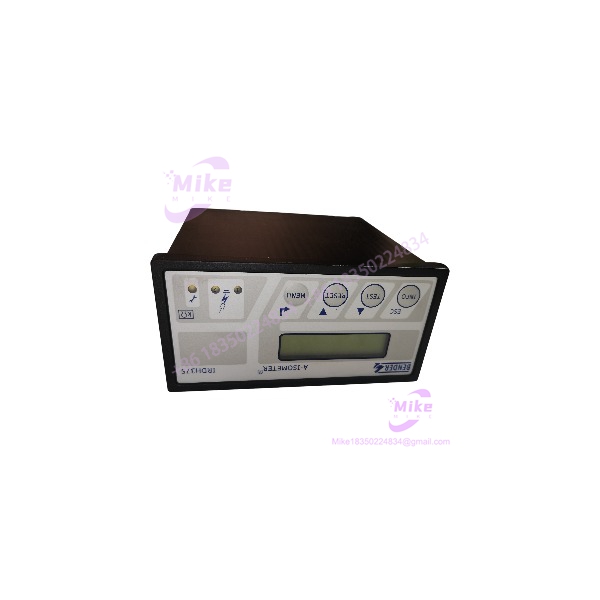
Bender IRDH375B-435 | BMS-Enabled Insulation Monitor
Product Introduction
An insulation fault in an unearthed electrical system can remain undetected until a second fault creates a more serious operating problem. The Bender IRDH375B-435 ISOMETER is designed to continuously monitor insulation resistance and signal when configured response thresholds are crossed.
The IRDH375B-435, article B91065004, adds BMS communication and event-history functions to the IRDH375 platform. It supports unearthed systems up to 793 VAC or 650 VDC and accepts an auxiliary supply of 88–264 VAC or 77–286 VDC. Its configurable current output supports 0–20 mA or 4–20 mA. For replacement procurement, match the full model, article number, wiring, and output configuration against the installed monitor.
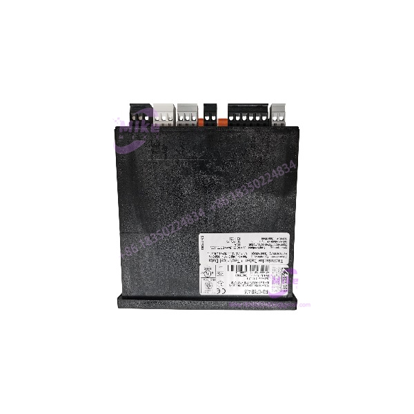
IRDH375B-435
Key Technical Specifications
- Manufacturer: Bender
- Model: IRDH375B-435
- Article Number: B91065004
- Product Series: ISOMETER IRDH375B
- Device Function: Insulation resistance monitoring
- Monitored AC System Voltage: 0–793 VAC, 3(N)AC systems
- Monitored DC System Voltage: 0–650 VDC
- Auxiliary Supply (AC): 88–264 VAC
- Auxiliary Supply (DC): 77–286 VDC
- Auxiliary Supply Frequency: 42–460 Hz
- Power Consumption: ≤14 VA
- Response Value Range: 1 kΩ–10 MΩ
- Alarm Thresholds: Two independently adjustable response values
- Analog Output: Selectable 0–20 mA or 4–20 mA
- Communication Interface: BMS via RS-485
- Memory: Real-time clock and history memory
- Measuring Voltage: ±50 V peak
- Maximum System Leakage Capacitance: 500 μF
- Relay Outputs: Two SPDT changeover contacts
- Protection Rating: IP30 enclosure / IP20 terminals
Specifications are based on Bender IRDH375/IRDH375B documentation. Confirm the physical nameplate and applicable manual revision before using these values as commissioning criteria.
Global Sourcing & Live-Test SOP
For insulation-monitoring equipment, visual inspection alone does not establish measurement accuracy or alarm performance.
Inbound Verification
- Confirm the complete IRDH375B-435 model marking.
- Verify OEM article number B91065004, where present.
- Photograph the front panel, nameplate, terminal markings, and housing.
- Inspect display, keys, terminals, and mounting features for damage.
- Record serial number and hardware revision where available.
Authenticity and Configuration Review
- Compare the nameplate and article number with Bender documentation.
- Verify auxiliary supply requirements before applying power.
- Confirm the monitored system type and voltage limits.
- Identify the configured analog output mode.
- Verify BMS wiring and system settings against the intended installation.
- Distinguish the standard IRDH375 from and W/BW variants.
Functional Validation
- Energize only with a verified compatible auxiliary supply.
- Check startup, display operation, and available self-test functions.
- Test insulation-monitoring response using a controlled, appropriate test setup.
- Verify alarm relay operation.
- Test the analog output in its configured mode.
- Verify BMS communication when suitable test equipment and configuration are available.
- Record test setup, settings, measured response, and results.
- Do not claim calibration or functional testing unless actually performed and documented.
ESD Protection and Shipment
- Protect the device from impact, moisture, and contamination.
- Secure terminal areas and mounting hardware.
- Use protective packaging suitable for electronic instrumentation.
- Include only accessories explicitly identified in the sale.
Field Engineer’s Pitfall Guide
- ❗ Do not confuse the -435 supply variant with -425 or -427. The -435 accepts 88–264 VAC or 77–286 VDC auxiliary power. Other suffixes have different supply ranges. Verify the complete model before energizing.
- ❗ Do not substitute the standard IRDH375 without checking the interface. The B version includes BMS communication, history memory, and a configurable current output. Confirm that the replacement supports the installed system’s communication and analog-input requirements.
- ❗ Verify the monitored-system limits and alarm settings. The device’s auxiliary supply is separate from the monitored circuit rating. Check both, and confirm response thresholds and relay logic before commissioning.
Intent-Driven FAQ
What isder used for?
It continuously monitors insulation resistance in unearthed AC and DC systems and provides alarms when configured response thresholds are crossed.
What is the OEM article number?
The documented articlefor is B91065004.
What auxiliary suppthe require?
The documented range is 88–264 VAC or 77–286 VDC. Verify the nameplate before applying power.
What is the difference between IRDHand ?
The B version adds a BMS interface, real-time clock/history memory, and a selectable 0–20 mA or 4–20 mA current output.
What system voltthe monitor?
The documented nominal range is 0–793 VAC or 0–650 VDC for supported unearthed systems.
the hot-swappable?
Do not assume hot-swap capability. Follow site electrical-safety procedures and Bender installation instructions.
What should I verify before purchasinlus ?
Confirm the complete model and article number, auxiliary supply range, analog output mode, BMS requirements, terminal condition, and documented test status. Verify warranty and included accessories with the seller.
Procurement Note
This listing describes theted , article B91065004. It does not imply that a specific surplus unit has been tested, calibrated, or supplied with a warranty. Confirm physical condition, included accessories, and test status before publishing.





