


Description
BENDER EDS460-D-1 | 2–10mA, 16–94VDC
Product Introduction
A fault in an unearthed industrial power system does not always announce itself with a dramatic shutdown. Sometimes the insulation deterioration is the warning. The BENDER EDS460-D-1 is designed for that situation: it evaluates insulation-fault signals and helps maintenance personnel locate the affected circuit rather than simply reporting that an insulation problem exists.
The EDS460-D-1 uses external W-series, WR-series, or WS-series measuring current transformers and provides a 2–10 mA response sensitivity for the EDS function. Its graphical LC display gives technicians local diagnostic information, while two relay outputs provide alarm signaling to the surrounding control or protection system. The unit supports AC 42–460 Hz supply operation and DC 16–94 V, making the -D-1 version particularly relevant to low-voltage control and industrial DC applications.
This is not a generic insulation monitor. The BENDER EDS460-D-1 belongs to a specific BENDER measurement architecture, so the external current-transformer type, system voltage, response threshold, and wiring arrangement should be checked before replacement.
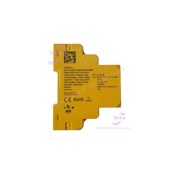
EDS460-D-1
Key Technical Specifications
| Parameter | Specification |
|---|---|
| Manufacturer | BENDER |
| Model | EDS460-D-1 |
| Series | ISOSCAN EDS460 |
| Product Type | Insulation Fault Locator / Evaluator |
| Application | Unearthed AC, AC/DC, and DC IT systems |
| Supply Voltage, AC | 16–72 VAC |
| Supply Voltage, DC | 16–94 VDC |
| Supply Frequency | 42–460 Hz |
| EDS Response Sensitivity | 2–10 mA |
| EDS Function Measuring Range | 1.5–50 mA |
| RCM Function Measuring Range | 100 mA–10 A |
| Measuring Channels | 12 per device |
| Maximum System Channels | 1,080 |
| Measuring CT Type | W…, WR…, WS… |
| CT Rated Insulation Voltage | 800 V |
| CT Monitoring | On/Off |
| CT Circuit Load | 10 Ω |
| Display | Backlit graphical LC display |
| History Memory | 300 data records |
| Password | Off / 0–999 |
| Language | German / English / French |
| Alarm Relays | 2 × changeover contact |
| Relay Operation | Normally energized or de-energized |
| Relay Electrical Endurance | 10,000 cycles |
| Relay Rating | Up to 5A at 230VAC, depending on utilization category |
| Response Delay | 0–24 seconds |
| Release Delay | 0–24 seconds |
| Full Channel Scan | Approximately 8–24 seconds |
| Operating Temperature | -25°C to +55°C |
| EMC | IEC 61326-2-4 |
| Protection at Terminals | IP20 |
| Mounting | DIN rail / screw mounting |
| Housing | Polycarbonate |
| Weight | <360 g |
| Article Number | B 9108 0001 |
Bender’s current documentation specifies the EDS460/490 family at 12 channels per device/system module and identifies the EDS460-D versions by graphical LC display. The EDS460-D-1 specifically corresponds to B 9108 0001.
Application Scenarios & Pain Points
Scenario: One Insulation Fault, Many Branch Circuits
Without fault-location evaluation:
An insulation-monitoring alarm tells the maintenance team that the IT system has a problem. Finding the actual feeder can then become a cabinet-by-cabinet troubleshooting exercise.
With the architecture:
The measuring current transformers identify fault-location signals on individual circuits, allowing the affected channel to be isolated much faster.
The device supports 12 measuring channels, while the overall EDS architecture can be expanded to as many as 1,080 channels.
Industrial DC Control Systems
The 16–94 VDC supply range the suitable for many industrial control environments where the monitoring electronics are powered from a DC control bus.
This matters when the insulation-monitoring device must remain compatible with an existing control cabinet rather than introducing another dedicated AC supply.
High-Frequency AC Systems
The specified supply frequency range reaches 460 Hz, while the EDS function itself supports DC and AC systems at 50/60/400 Hz. That broad operating envelope is useful in specialized industrial and electrical installations where standard 50/60 Hz assumptions do not apply.
Historical Fault Analysis
Intermittent insulation faults are difficult to troubleshoot if the alarm disappears before maintenance arrives.
The 300-record history memory on the -D version gives technicians a record of stored events, providing useful evidence when a fault is intermittent rather than continuously present.
Response-Time Tuning
The family provides adjustable 0–24 second response and release delays. That allows the monitoring behavior to be coordinated with the characteristics of the monitored system instead of treating every transient as an immediate fault condition.
QA & Live Testing SOP
For the , a power-on test alone proves very little. The measurement circuit and external current-transformer interface are part of the functional system.
Recommended inspection procedure
- Identity verification
- Confirm on the nameplate.
- Verify article number B 9108 0001.
- Record serial number and hardware markings.
- Physical inspection
- Inspect the LC display, terminal blocks, housing, DIN mounting mechanism, and screw terminals.
- Check for cracked polycarbonate, corrosion, contamination, or signs of overheating.
- Supply test
- Apply a controlled supply within 16–94 VDC or 16–72 VAC.
- Verify normal startup and display operation.
- Confirm that the device does not generate unexpected alarm states during initialization.
- Display and menu test
- Check graphical display operation.
- Verify menu navigation.
- Confirm parameter access and alarm indication.
- Measurement-channel test
- Use the appropriate BENDER-compatible test arrangement and external measuring current transformer.
- Verifythe detects the expected measurement signal.
- Relay test
- Verify both changeover relay outputs.
- Check the selected normally energized/de-energized operating behavior.
- Communication/interface inspection
- Verify the RS-485/BMS connection where the installation uses BMS integration.
- Confirm termination and addressing configuration before connecting to a live system.
- Packaging
- Protect the LC display and terminal area against impact.
- Use ESD-conscious electronic packaging and sufficient cushioning for shipment.
Bender specifies RS-485/BMS communication, a cable length up to 1,200 m, and a switch-selectable 120 Ω termination resistor for the /490 architecture.
Field Engineer’s Pitfall Guide
❗ Do Not Sute With EDS461-D-1
They look like members of the same family, but the response sensitivity is different.
2–10 mA
EDS461-D-1: 0.2–1 mA
That is a tenfold difference in the response range. Selecting the wrong version can fundamentally change the behavior of the insulation-fault detection system.
❗ Do Not Confuse “-1” and “-2”
The supply configuration is different.
16–94 VDC / 16–72 VAC
70–276 VAC/DC
The suffix is therefore an electrical configuration identifier, not simply a revision number. Verify the cabinet supply before installing a replacement.





