

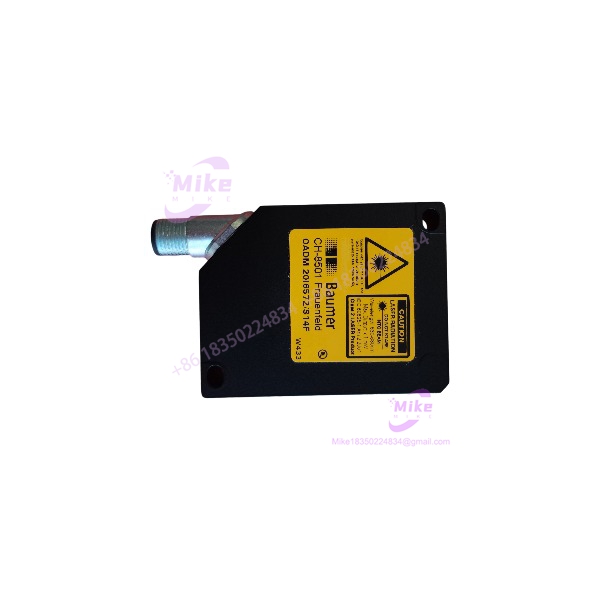
Description
Baumer OADM 20I6572/S14F Laser Distance Sensor, 50–300 mm, Analog Output
Product Introduction
In automated production, distance measurement errors can lead to inconsistent positioning, incorrect material handling, and unnecessary machine stops. The Baumer OADM 20I6572/S14F addresses these requirements with laser-based, non-contact measurement and analog output signals that can be evaluated by a PLC, industrial controller, or compatible measurement system.
The sensor supports teach-in adjustment through either its onboard button or an external input. A line-shaped laser beam helps monitor a defined section of a target surface, while the integrated red LED indicators provide operating-status and lens-contamination information. The die-cast zinc housing, glass optical front, and IP67 protection rating support use in suitable industrial environments.
This model is worth evaluating for dimensional monitoring, part-position feedback, material-height checks, and similar measurement tasks within its specified operating range. However, it should not be treated as a universal replacement for every photoelectric sensor. The target material, surface reflectivity, ambient lighting, mounting geometry, and required measurement accuracy all affect application suitability.
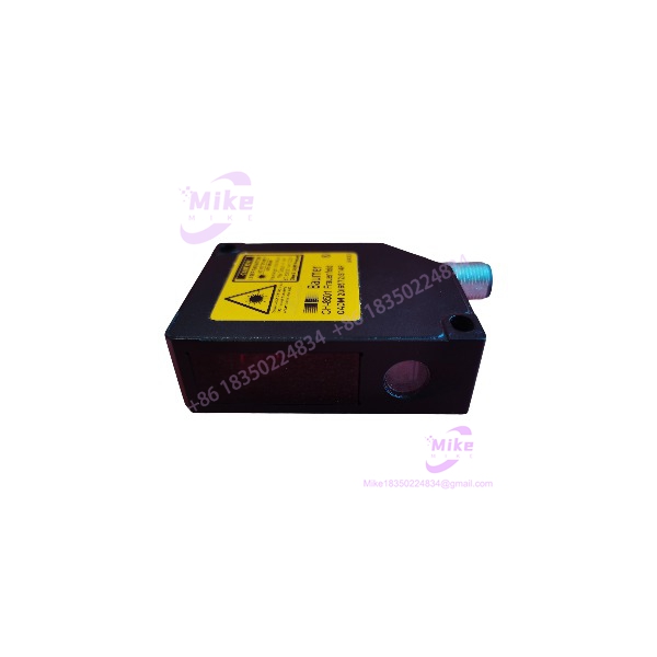
OADM 20I6572/S14F
Key Technical Specifications
The following specifications are published for the Baumer OADM 20I6572/S14F.
- Manufacturer: Baumer
- Product type: Laser distance sensor / photoelectric distance sensor
- Measuring range: 50–300 mm
- Output signals: 4–20 mA and 0–10 VDC
- Supply voltage: 12–28 VDC
- Maximum no-load current consumption: 100 mA
- Response and release time: Less than 0.9 ms
- Resolution: 10–330 µm, depending on measurement conditions
- Linearity error: ±0.03 to ±1 mm, depending on operating conditions
- Light source: Pulsed red laser diode
- Wavelength: 650 nm
- Laser classification: Class 2
- Beam type: Line
- Beam width: 2.5 mm
- Beam height: 4–12 mm
- Temperature drift: Less than 0.03% of the sensing distance per kelvin
- Alarm output: PNP
- Protection features: Short-circuit protection and reverse-polarity protection for the supply
- Housing material: Die-cast zinc
- Optical front: Glass
- Connection: Rotatable M12, 8-pin connector
- Ingress protection: IP67
- Operating temperature: 0 to +50 °C
- Dimensions: Approximately 20.6 mm wide × 65 mm long × 50 mm deep
Important electrical note: The analog current and voltage outputs have different load requirements. The current-output load must satisfy the manufacturer’s supply-voltage-dependent limit, while the voltage output requires a load resistance greater than 100 kΩ. Confirm the selected output mode and the receiving controller’s input specifications before commissioning.
The published linearity and resolution figures are not interchangeable. Actual performance depends on target properties and measurement conditions; do not assume the smallest stated error applies throughout the full measuring range.
Application Scenarios & Pain Points
Non-contact position measurement
Use the sensor to monitor the position of a moving component or fixture without physical contact. This can help reduce mechanical wear associated with contact-based measurement methods. Confirm that the target remains within the 50–300 mm sensing range throughout its full movement.
Part height and dimensional monitoring
An analog signal can provide continuous measurement data for PLC-based monitoring or process control. Engineers should validate the sensor against reference measurements using the actual part material and surface finish before setting acceptance limits.
Material handling and conveyor systems
Distance feedback can help detect changes in material position or height during automated transport. Stable mounting and control of vibration are important because movement of the sensor itself can appear as a change in measured distance.
Machine automation and equipment retrofits
The OADM 20I6572/S14F may be considered for replacing an existing analog laser sensor where the sensing range, electrical interface, connector, and mounting geometry match. Check the controller’s analog input configuration carefully: a 4–20 mA input is not interchangeable with a 0–10 V input without suitable hardware and configuration.
Practical limitation: The manufacturer’s listed ambient-light immunity is below 8 kLux for this model. Applications exposed to strong illumination, changing reflective surfaces, or direct sunlight require testing under representative operating conditions.
QA & Live Testing SOP
For used, surplus, or replacement inventory, request a documented inspection rather than relying on appearance alone.
1. Verify model identity. Confirm that the label reads OADM 20I6572/S14F. Inspect the housing, optical window, connector, and mounting surfaces for damage or evidence of unauthorized repair.
2. Inspect the optical path. Check for contamination, scratches, condensation, or damage to the glass front. Clean only with an appropriate method that will not damage the optical surface.
3. Check the electrical interface. Verify the 12–28 VDC supply requirement and identify the correct M12 connector pinout from the manufacturer’s wiring diagram. Do not assign wires based on color alone.
4. Power the sensor safely. Use a current-limited DC supply within the specified voltage range. Check the green power indicator and investigate any red contamination or alarm indication.
5. Test measurement response. Place a suitable target at several known distances within the 50–300 mm range. Compare the output against a calibrated reference and record repeatability, response, and any instability.
6. Verify analog outputs. Test the 4–20 mA and 0–10 VDC outputs using compatible measurement equipment and the correct load conditions. Confirm output scaling and signal behavior against the manufacturer’s documentation.
7. Check the alarm and teach-in functions. Verify external teach-in or button operation as applicable, and test the PNP alarm output using a compatible input circuit.
8. Record acceptance results. Document the model and serial number, test distances, supply voltage, output readings, visual condition, and pass/fail status. Retain the results with the equipment maintenance record.
These are recommended incoming-inspection and commissioning steps, not a claim that a particular unit has already been tested. Actual test results must be supplied by the seller or generated during inspection.
Field Engineer’s Pitfall Guide
- Wrong output type: The sensor supports current and voltage analog signals. Confirm which output the application uses and whether the existing PLC analog input supports it.
- Incorrect wiring: The M12 connector has eight pins. Use the model-specific connection diagram before applying power; incorrect connections can damage the sensor or connected equipment.
- Unverified measurement accuracy: The published resolution varies with conditions, and linearity error can vary across the measurement range. Validate performance using the actual target rather than relying on a single bench reading.
- Poor target or mounting geometry: A laser line does not eliminate the effects of target reflectivity, surface shape, alignment, vibration, or ambient illumination. Test the sensor at the installed angle and distance.
- Environmental mismatch: IP67 protection does not mean unrestricted operation in every environment. The published operating temperature is 0 to +50 °C, and condensation, optical contamination, and exposure outside the specified limits still require attention.
- Assuming direct interchangeability: Before replacing another sensor, compare its measuring range, analog output, supply voltage, connector pinout, mounting dimensions, and control-system scaling.
- Ignoring laser safety: This is a Class 2 laser product. Follow the manufacturer’s safety instructions and avoid staring into the beam.
Intent-Driven FAQ
Q1: What is the measuring range of the Baumer OADM 20I6572/S14F?
Its specified measuring range is 50–300 mm. Ensure the entire required operating distance falls within the permitted range.
Q2: What output signals does this sensor provide?
The published analog output signals are 4–20 mA and 0–10 VDC. Verify the output configuration and receiving input before installation.
Q3: Can the OADM 20I6572/S14F connect to a PLC?
Yes, provided the PLC or remote I/O system has a compatible analog input and the wiring, scaling, supply, and load requirements are satisfied.
Q4: Is this sensor suitable for a wet industrial environment?
Its IP67 rating indicates a specified level of protection against dust ingress and temporary immersion under defined test conditions. Suitability still depends on the installation, temperature, cleaning process, and chemical exposure.
Q5: Does the sensor require calibration?
The required verification procedure depends on the application. For critical dimensional measurements, compare readings against calibrated reference distances and establish an appropriate validation interval.
Q6: What should I confirm before purchasing a replacement?
Check the full model number, physical condition, output requirements, connector and pinout, measuring range, mounting dimensions, and required accuracy. For used equipment, request actual functional test results where available.
Q7: What information should I provide when requesting a quotation?
Provide the complete model number, required quantity, destination country, preferred condition (new, surplus, or used), and any required inspection or documentation. If replacing an installed unit, include the existing sensor’s wiring and application details.
Q8: What is the key procurement check for the Baumer OADM 20I6572/S14F?
Confirm that the exact model and analog interface meet the application’s requirements, then establish the unit’s condition and test status before committing to a replacement. Published specifications describe the model; they do not independently verify the condition or authenticity of an individual listing.





