


Description
Acromag 651T-0600 | Isolated 2-Wire Transmitter Module
Dynamic Product Introduction
Ground loops and common-mode voltage spikes are notorious for corrupting analog telemetry across long cable runs between field instrumentation and control room PLC analog cards. When raw sensor signals share a common return path with heavy industrial drives, voltage offsets degrade measurement accuracy or destroy delicate input channels. The Acromag 651T-0600 eliminates these ground loop differential errors by inserting a high-integrity 1500V galvanic isolation barrier between the field transmitter and the receiving PLC/DCS node.
Operating strictly as a two-wire loop-powered device, the 651T-0600 eliminates the need for local AC or auxiliary DC power supplies at the mounting panel. Its high-density 12.5mm DIN rail housing allows control panel builders to pack dozens of isolated channels into crowded cabinets without generating localized heat spots. For facility maintenance engineers troubleshooting noisy instrumentation loops or replacing legacy field transmitters, keeping a pre-calibrated 651T-0600 on hand prevents costly signal drift and protects downstream control hardware.
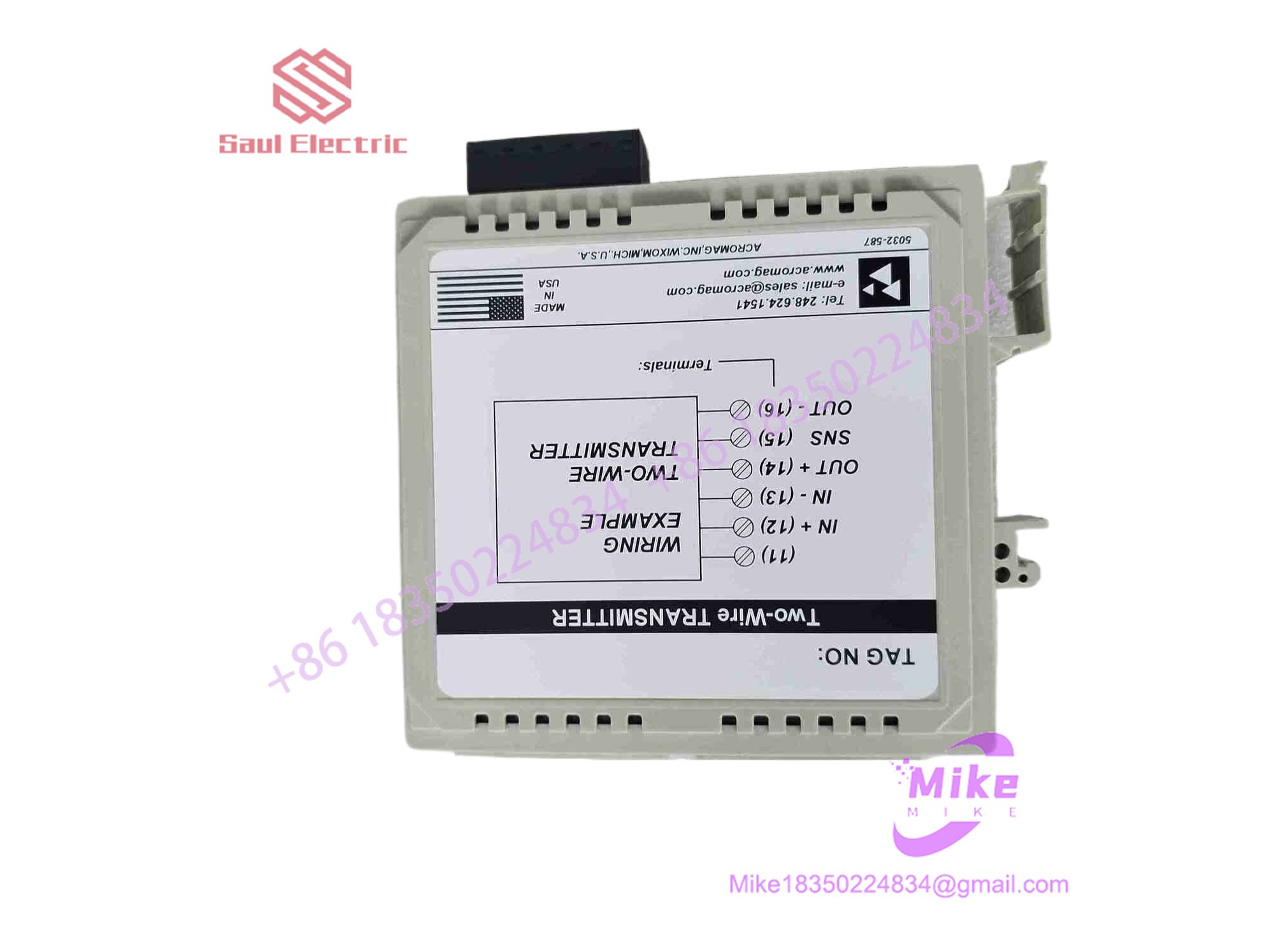
651T-0600
Key Technical Specifications
| Parameter | Technical Specification |
| Input Signal Range | 4 to 20 mA DC (Internal 50 ohm shunt load) |
| Output Signal Range | 4 to 20 mA DC (2-Wire loop-powered) |
| Power Supply Voltage | 12 to 50 V DC loop supply (12 to 30 V DC Class 2) |
| Galvanic Isolation | 1500 V AC RMS (Input to Output/Power) |
| Accuracy / Linearity | ±0.1% of calibrated span |
| Ambient Temperature Drift | Less than ±0.01% of span per °C |
| Zero & Span Adjustment | Multi-turn potentiometers mounted on front bezel |
| Housing Style | Slimline 12.5mm DIN rail mount (35mm EN 50022 rail) |
| Operating Temperature | -25°C to +70°C (-13°F to 158°F) |
| Agency Approvals | CE marked, UL/cUL Listed (Class I, Div 2, Groups A, B, C, D) |
Global Sourcing & Live-Test SOP (Transparency Core)
To ensure field readiness for replacement instrumentation, every surplus and refurbished signal conditioner undergoes strict bench test validation before leaving our facility:
Inbound Verification & Physical Audit
- Traceability & Housing Review: Verification of original Acromag serial tags, terminal block threads, and casing latches to rule out gray-market or damaged stock.
- Component Inspection: High-magnification optical audit of internal PCB solder joints, isolation transformers, and potentiometer tracks for signs of thermal fatigue or moisture exposure.
Live Simulation Setup
- Loop Circuit Integration: The 651T-0600 is wired into a calibrated 24V DC loop-powered test bench using a high-precision Fluke current calibrator as the input source.
- Zero & Span Verification: Driving 4.00 mA and 20.00 mA inputs to verify baseline output linearity across five calibration points (0%, 25%, 50%, 75%, 100%).
Diagnostic & High-Voltage Testing
- Galvanic Isolation Test: Applying a 1500V AC test potential between input and output terminals for 60 seconds to verify zero breakdown or leakage current across the isolation transformer.
- 24-Hour Thermal Run: Operating the transmitter under maximum loop voltage (30V DC) at 50°C ambient inside a burn-in chamber to confirm thermal stability.
Final Prep & Export Packaging
- Calibration Logging: Trimming zero and span settings to standard factory defaults and attaching a test certificate.
- ESD Safe Protection: Sealed in anti-static shielding bags with desiccant packaging prior to international dispatch.
The Field Engineer’s Pitfall Guide
❗ Polarity Inversion & Reverse Loop Wiring
While the 651T-0600 features internal protection diodes, landing loop power wires with reversed polarity prevents the internal current regulator from energizing. This results in a dead 0mA output on the receiving PLC analog input card, often misdiagnosed as a failed field sensor.
(In actual plant callouts, I’ve seen technicians replace perfectly good transmitters simply because someone reversed the loop positive and negative leads during terminal strip re-wiring).
❗ Exceeding Maximum Loop Burden Resistance
Because the 651T-0600 drops voltage to power its internal signal processing circuits, you must calculate total loop compliance voltage. Attempting to drive a high-resistance load (e.g., >800 ohms) using a low 12V DC power supply will cause the output current to clamp below 20mA during high-signal conditions.
❗ Over-Torquing Front Panel Potentiometers
The Zero and Span trimpots on the front panel are delicate multi-turn components. Forcing these pots past their mechanical end-stops with an improper screwdriver size will strip the internal wiper mechanism, requiring full PCB-level replacement.
Intent-Driven FAQ
Does the 651T-0600 require a separate 120V AC or 24V DC power connection?
No. The module is entirely loop-powered from the output side 2-wire loop (12–50V DC). It operates by modulating the current drawn from the receiving device’s loop power supply.
Can I use the 651T-0600 in hazardous locations?
Yes. The 651T-0600 carries UL/cUL Class I, Division 2, Groups A, B, C, and D ratings, making it suitable for hazardous location panels when installed per National Electrical Code guidelines.
How do I adjust the calibration if my input loop drifts?
Use an accurate current source to supply 4.00mA to the input terminals and adjust the front-panel “ZERO” potentiometer until your meter reads 4.00mA on the output. Then supply 20.00mA and adjust the “SPAN” pot until the output reads 20.00mA.
Will this transmitter pass HART protocol signals through the isolation barrier?
No. Standard 600T series analog isolators attenuate high-frequency HART digital FSK signals. If your application requires HART passthrough, you must select a HART-transparent isolator variant.
What warranty covers this transmitter when purchased as tested surplus?
All fully certified surplus and replacement Acromag 651T-0600 units include a standard 12-month operational warranty covering signal accuracy, loop current regulation, and galvanic isolation integrity.





