


Description
Pacific Scientific 6420-001-N-N | Stepper Drive 10A RMS 75VDC
Architect’s Product Breakdown
The Pacific Scientific 6420-001-N-N handles heavy-duty motion applications that require substantial phase current without sacrificing microstepping resolution. Serving as the primary power amplifier between a high-speed indexer and a large NEMA-frame stepper motor, it translates low-level pulse trains into precise current vectors. Operating via an internal 20 kHz pulse-width modulation scheme, the drive significantly suppresses mid-range motor resonance and smooths low-speed velocity ripple under heavy dynamic loads.
Panel installation demands rigorous thermal planning because this higher-capacity variant pushes considerable current through its output stage. Cabinet designers must account for convective air currents to prevent internal ambient conditions from crossing the 60 °C threshold. Field replacements are straightforward via robust screw terminals and physical DIP switches, though technicians must precisely configure the phase current limits to match the specific thermal envelope of the driven motor winding.
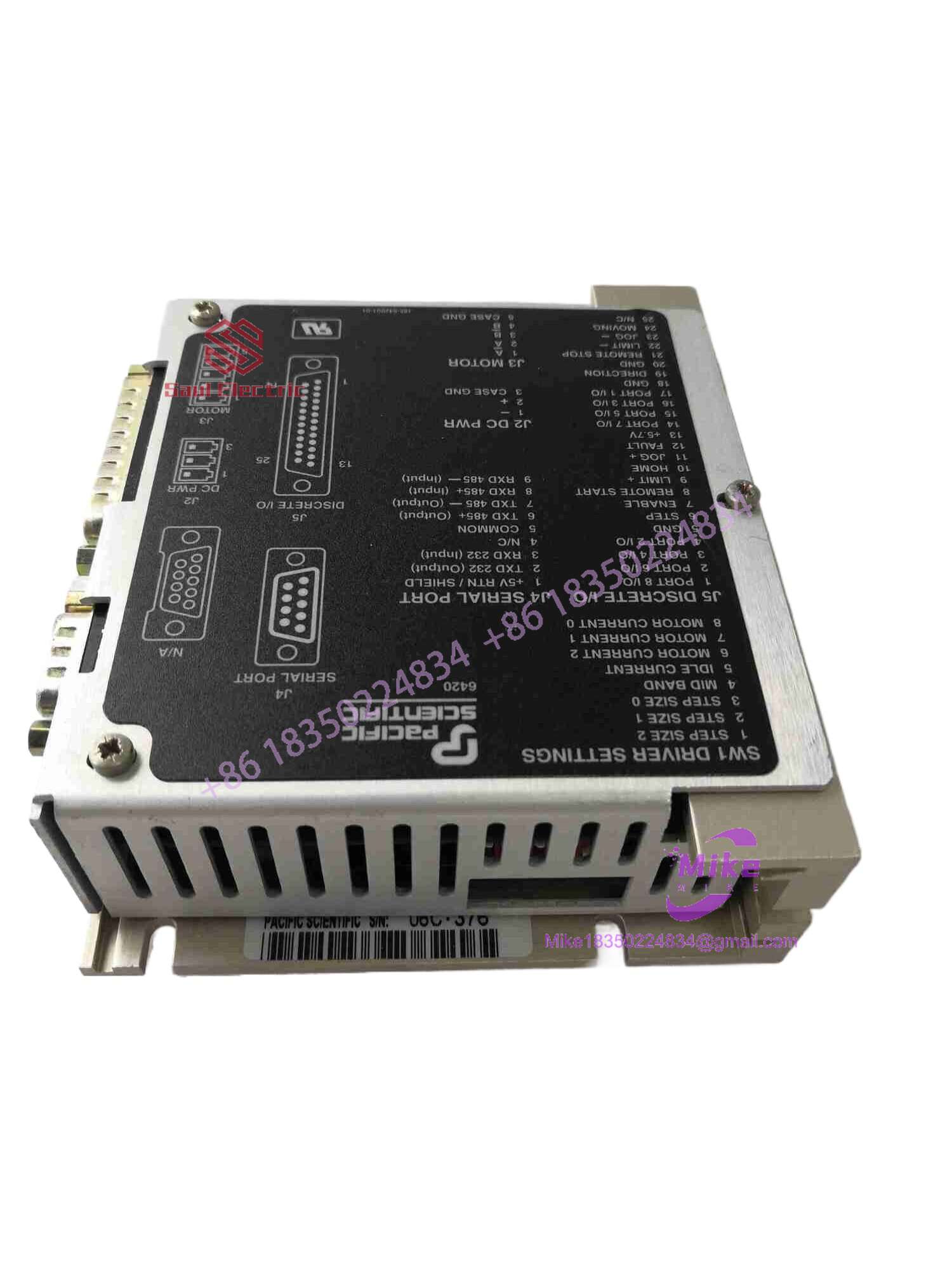
6420-001-N-N
Key Technical Specifications
| Parameter | Specification |
| Input Voltage Range | 24 to 75 VDC |
| Continuous Phase Current | 10.0 A RMS |
| Peak Phase Current | 14.1 A Peak |
| Max Step Frequency | 2.0 MHz (Digital Filter Off) |
| Minimum Step Pulse Width | 250 ns |
| Max Microstepping Resolution | Up to 51,200 steps/rev (for 1.8° motor) |
| Chopper Frequency | 20 kHz |
| Overvoltage Trip Threshold | 83 VDC |
| Idle Current Reduction | 50% automatic reduction when stationary |
| Enclosure Dimensions | 5.0 in x 2.5 in x 4.3 in |
| Max Operating Chassis Temp | 60 °C |
| Connectors | 3-contact power, 5-contact motor screw terminals, 9-socket D-Sub logic |
Field Engineer’s Pitfall Guide
- WARNING: Inductive Kickback on Power Down. Cutting the DC bus supply while the motor is spinning at high velocities turns the stepper into an unregulated generator. Without an adequate bus clamp or bleeding circuit, the resulting voltage spike will instantly puncture the output MOSFETs.
- CAUTION: Current Limit Mismatches. Do not assume default factory DIP switch settings are safe for your specific motor. Dialing the continuous phase switch beyond the motor manufacturer’s winding rating will cause rapid thermal saturation and demagnetize the rotor magnets.
- NOTICE: Logic Grounding Noise. The 9-socket D-Sub control port is vulnerable to electromagnetic interference in dense industrial panels. Failing to tie cable drain wires to a dedicated earth ground plane will result in intermittent step loss and position drift.
QA & Testing SOP
- Visual & Origin Inspection: Verified against OEM data sheets for physical integrity, correct connector labeling, and uncompromised internal circuit boards.
- Live Test Bench Environment: Powered up on a dedicated test fixture using a regulated 24–75 VDC bench supply to verify internal logic rails and capacitor health.
- Handshake & I/O Simulation: Pulse, direction, and enable signals are driven through the D-Sub port at frequencies up to 2.0 MHz to validate optocoupler response and isolation.
- Thermal & Load Run: Subjected to a rigorous multi-hour burn-in cycle under a simulated 10.0 A RMS resistive-inductive load to check PWM switching stability and heat dissipation.
- Packaging: Wrapped in static-dissipative shielding material and packaged with high-density cushioning to prevent transit damage.
Technical FAQ
Can I hot-swap this module while the process is running?
No. Disconnecting the motor leads or main power inputs while energized creates high-energy inductive arcing that will destroy the output switching bridge. Always cut power and verify bus capacitor discharge before touching terminals.
Do I need to reconfigure DIP switches when replacing an older unit?
Yes. Always verify that the physical switch settings on the new unit match the exact current requirements, step resolutions, and damping configurations of your specific motion axis. Copying settings blindly from a different machine layout can cause mechanical binding.
Why does the drive shut down during heavy deceleration profiles?
If the kinetic energy of a high-inertia load dumps too much regenerative current back into the DC bus, it will exceed the 83 VDC overvoltage protection threshold and trip the drive. Ensure your power supply setup includes appropriate bus dissipation components.
Does this unit retain configuration settings after power loss?
Yes. All operational parameters—including microstepping resolution and current scaling—are handled via physical hardware DIP switches on the housing, requiring no volatile memory batteries or firmware flashing.





