


Description
Giddings & Lewis 503-26606-21 | Legacy Motion Control Interface Board
Dynamic Product Introduction
Intermittent axis dropouts or position feedback faults on a large Giddings & Lewis machine tool can halt an entire production floor. The Giddings & Lewis 503-26606-21 serves as a crucial signal routing and interface link within legacy PiC-series control racks, bridging raw field sensor feedback directly into the system processor.
Built to withstand heavy industrial electrical noise, this board isolates sensitive logic circuits while ensuring deterministic signal paths between servo drives and the main CPU. Swapping out a thermally worn or trace-damaged 503-26606-21 module eliminates ghost tracking errors, restores reliable backplane communication, and keeps your high-value machining centers running with minimal downtime.
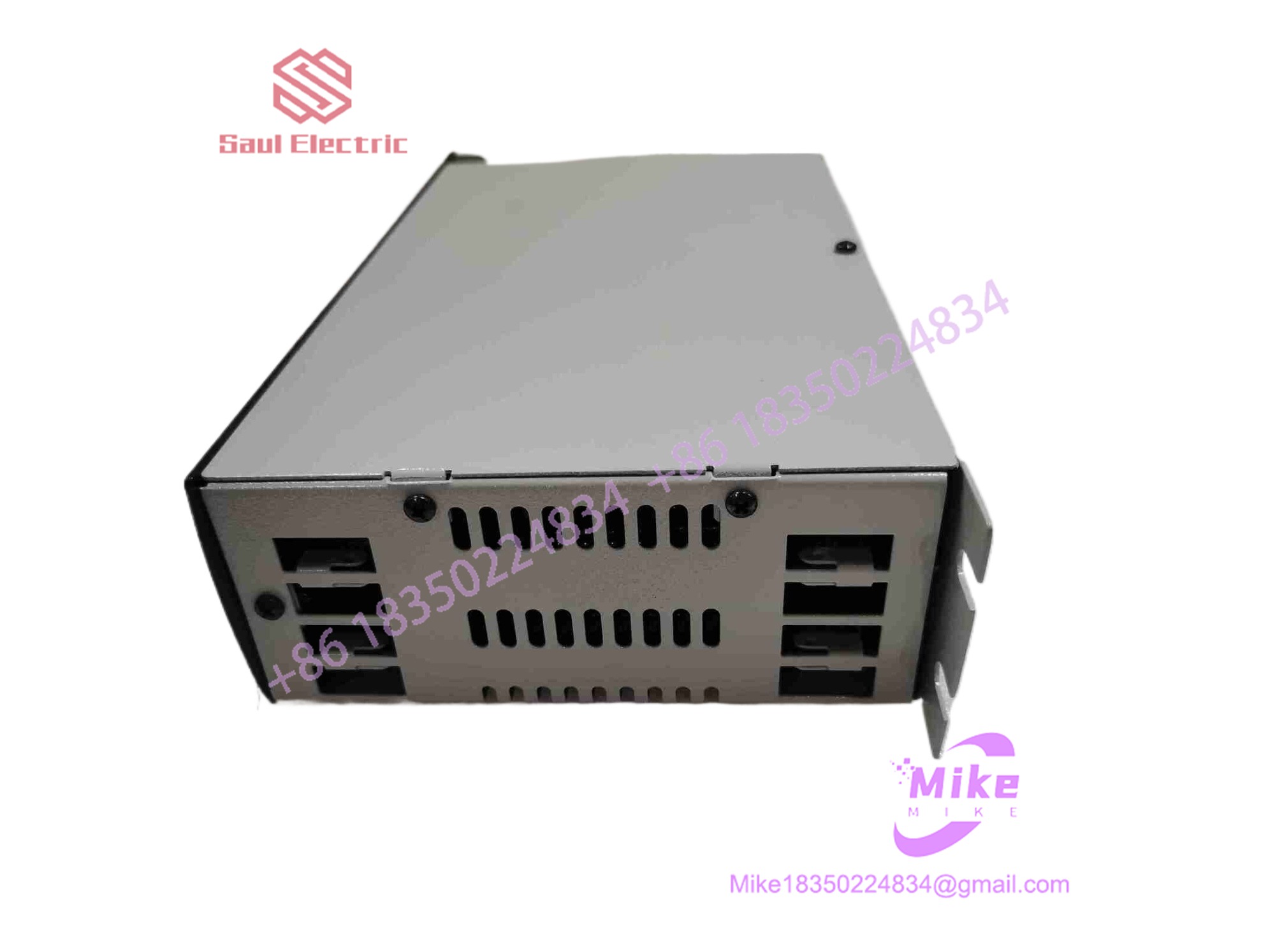
503-26606-21
Key Technical Specifications
| Parameter | Specification Detail |
| Part / Catalog Number | 503-26606-21 |
| OEM Manufacturer | Giddings & Lewis (G&L Motion Control) |
| System Family | G&L PiC900, PiC90, and legacy CNC control racks |
| Module Type | Motion Control / System Interface Board |
| Bus Interface | Proprietary G&L multi-pin card-edge backplane connector |
| Operating Power | Supply rails drawn from rack backplane (+5 VDC, ±12 VDC) |
| Operating Temperature | 0°C to +55°C (32°F to 131°F) |
| Construction | Multi-layer heavy-duty FR-4 PCB with gold-plated contact pads |
Global Sourcing & Live-Test SOP (Transparency Core)
Deploying legacy automation hardware into active manufacturing lines requires rigorous testing to guarantee operational stability. Here is how we validate every incoming 503-26606-21 unit before dispatch:
Inbound Verification
- High-magnification optical inspection of card-edge contacts, surface-mount components, and trace paths to identify physical damage, corrosion, or thermal stress.
- Cross-referencing board part numbers (
503-26606-21) and revision stampings against original G&L technical manifests.
Live Simulation & Bench Handshake
- The module is installed into an authentic Giddings & Lewis test rack equipped with active CPU and servo interface modules.
- Signal continuity across all backplane pin rows and onboard routing logic is monitored using a multichannel logic analyzer.
Load Diagnostics & Thermal Burn-In
- Simulated multi-axis movement programs are executed continuously to load onboard bus drivers and signal paths.
- The board undergoes a continuous thermal run at 50°C to stress passive components and verify trace stability under high operating temperatures.
Final Prep
- Gold card-edge fingers are cleaned using isopropyl solvent and treated with an anti-oxidation contact preserver.
- Sealed in static-shielding ESD packaging with protective edge covers applied.
The Field Engineer’s Pitfall Guide
❗ Confusing Suffix Revision Variants (-21 vs. Earlier Suffixes):
The -21 designator specifies a particular hardware revision and component population on the 503-26606 base board. Replacing a -21 unit with a lower revision (such as a -10 or -12) can leave specific signal channels unrouted or introduce timing discrepancies in sensitive motion control loops.
❗ Card Insertion Angle and Connector Damage:
Legacy G&L card cages rely on precise guide rails. Inserting the 503-26606-21 at an angle or forcing it into an unaligned backplane socket can strip or bend the thin gold contact fingers along the edge of the card—honestly, I’ve seen plant technicians destroy a fresh replacement board in seconds by forcing a jammed module into place.
❗ Ignoring Rack Voltage Health:
System interface boards often experience premature component failure due to high AC ripple or voltage drift coming from an aging rack power supply. Always measure the primary 5 VDC rail with an oscilloscope or multimeter to verify clean, regulated power before sliding in the new card.
Intent-Driven FAQ
Does the Giddings & Lewis 503-26606-21 store system parameters or programs?
No. The 503-26606-21 functions as a hardware interface and signal processing board. User logic, axis parameters, and system software reside in non-volatile flash memory on the primary CPU card.
Can I hot-swap this board while the G&L control system is powered on?
No. The G&L PiC rack must be completely powered down before removing or inserting the 503-26606-21. Live insertion can cause electrical arcing across the backplane edge connectors and permanently damage onboard logic ICs.
How do I troubleshoot intermittent communication errors associated with this card?
Inspect the rear gold card-edge fingers for discoloration or oxidation. Cleaning the contacts with an electronics contact cleaner and verifying that the rack power supply provides steady, ripple-free 5 VDC power typically resolves intermittent connection issues.
What is the typical failure mode for these legacy motion interface cards?
Thermal stress on onboard bus driver ICs, degraded solder joints caused by decades of machine vibration, and contact wear on edge connectors are the primary failure points in field environments.
What warranty coverage is provided with surplus or refurbished units?
Every Giddings & Lewis 503-26606-21 card passing through our QC bench test protocol includes a full 1-year replacement warranty covering backplane signal integrity, component longevity, and operational stability.





