


Description
244-704-000-042-A2-B01-C10-D20-E2-F10000-C0-H0-I0 Vibro-Meter
Dynamic Product Introduction
Critical rotating machinery—such as gas turbines, steam turbines, heavy industrial pumps, and compressors—requires continuous vibration monitoring to detect imbalance, bearing wear, and mechanical fatigue before catastrophic failures occur. The Meggitt Vibro-Meter IPC704 (PNR 244-704-000-042) is an industrial-grade signal conditioner engineered to interface piezoelectric transducers (accelerometers and dynamic pressure sensors) with plant-wide Distributed Control Systems (DCS) and Programmable Logic Controllers (PLCs).
By converting raw charge signals (pC/g) into standardized analog currents or voltages, the IPC704 eliminates signal degradation over long cable runs between hazardous field locations and control rooms. The extensive alphanumeric configuration code (A2-B01-C10-D20-E2-F10000-G0-H0-I0) defines specific hardware options including input sensitivity, high-pass/low-pass filter cutoffs, output signal scaling, explosion-protection ratings, and mounting options. Installing an exact-match replacement IPC704 guarantees that alarm setpoints and vibration trend metrics in your machinery protection system remain perfectly calibrated.
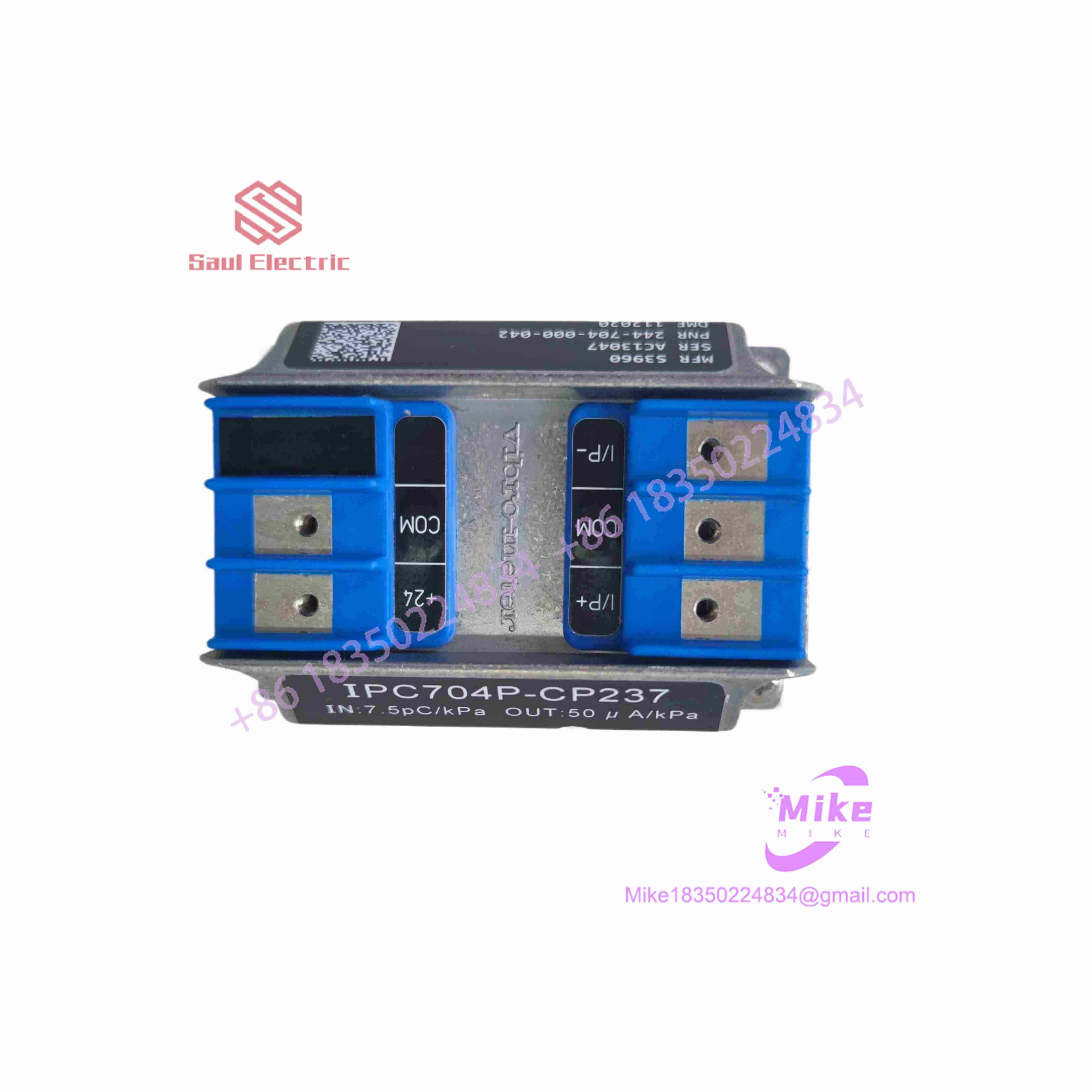
244-704-000-042-A2-B01-C10-D20-E2-F10000-C0-H0-I0
Key Technical Specifications
| Parameter | Technical Specification |
| OEM Manufacturer | Meggitt / Vibro-Meter |
| Base Hardware P/N | 244-704-000-042 (IPC704 Signal Conditioner) |
| Transducer Inputs | Piezoelectric Charge Accelerometers (e.g., CA series) or Dynamic Pressure Transducers |
| Input Sensitivity (A/B Options) | Configured for specific transducer sensitivity (e.g., 10 pC/g or 100 pC/g) |
| Frequency Filtering (C/D Options) | High-Pass (e.g., 10 Hz) and Low-Pass (e.g., 1000 Hz / 10 kHz) band-pass filters |
| Analog Output (E Option) | Standard 4–20 mA current loop and/or proportional voltage output (0–10V / raw dynamic signal) |
| Power Supply | +24 VDC nominal (galvanically isolated input/output/power) |
| Operating Temperature | -40°C to +85°C (-40°F to +185°F) |
| Enclosure / Mounting | Aluminium housing with DIN-rail adapter or direct plate-mount options |
Global Sourcing & Live-Test SOP (Transparency Core)
To ensure field readiness when replacing critical condition monitoring hardware, every stock or surplus Vibro-Meter 244-704-000-042 unit undergoes a full calibration verification process prior to dispatch:
Inbound Inspection & Configuration Audit
- Ordering Code Verification: Cross-referencing all sub-codes (
A2,B01,C10,D20,E2,F10000, etc.) against the physical unit rating plate to confirm exact filter cutoffs, sensitivity factors, and output ranges match the requirement. - Terminal & Enclosure Audit: Inspected under optical magnification for corrosion on screw terminals, intact housing seals, and undamaged mounting clips.
Dynamic Signal Simulation Bench Test
- Precision Charge Generation: Applying a calibrated pC (picocoulomb) test signal across the input terminals using a high-precision charge generator to simulate accelerometer output across varying frequencies.
- Filter Curve Verification: Sweeping signal frequencies from 1 Hz to 20 kHz on an oscilloscope/spectrum analyzer to verify that high-pass and low-pass cutoff points match the specified option codes.
Output & Thermal Burn-In
- Loop Output Accuracy: Measuring 4–20 mA loop current precision across 0%, 50%, and 100% full-scale vibration inputs to verify linearity within OEM tolerance (typically <1%).
- 24-Hour Thermal Drift Run: Powering the module under full load in a thermal test chamber to confirm continuous thermal stability and zero calibration drift.
The Field Engineer’s Pitfall Guide
❗ Mismatched Configuration Sub-Codes
The base part number 244-704-000-042 identifies the physical housing platform, but the trailing sub-codes (A2-B01-C10...) specify the internal analog filter frequencies and gain calibration. Installing a unit with incorrect C or D filter settings will cause false high-vibration alarms or fail to trip during actual high-frequency bearing faults.
❗ Ground Loops on Shielded Transducer Cabling
Piezoelectric accelerometers and charge amplifiers are extremely sensitive to ground loops. Ensure cable shields are grounded at a single point (typically at the IPC704 frame or safety barrier) and isolated at the sensor head to avoid 50/60 Hz line noise riding on the vibration signal.
❗ Wiring Voltage Supply to Output Terminals
Connecting the 24 VDC power supply across the raw signal voltage output terminals instead of the designated power rail will destroy the internal output line driver. Always verify terminal block pinouts against the IPC704 wiring diagram prior to powering up.
Intent-Driven FAQ
What does the “” designation stand for?
IPC stands for Signal Conditioner (Industrial Piezoelectric Conditioner) in the Vibro-Meter product line, specifically configured for processing dynamic charge and voltage signals from industrial sensors.
Can I reconfigure the filter frequencies of a 244-704-000-042 in the field?
Most units have factory-hardwired or internal solder-bridge/resistor-set configurations determined at the time of manufacture (encoded in the full option string). Field adjustment usually requires factory recalibration or internal board modification.
How does the 244-704-000-042 interface with a DCS or SCADA system?
The unit provides a 4–20 mA current loop output proportional to overall vibration velocity or acceleration, which wire directly into standard DCS/PLC analog input cards.
What is the difference between raw signal output and processed output on the ?
The raw output delivers the unfiltered AC dynamic signal (for FFT frequency analysis via portable vibration analyzers), while the main output delivers a processed DC level (4–20 mA) representing the RMS or Peak overall vibration level for alarm monitoring.
What warranty is provided with certified replacement units?
Fully tested surplus or replacement Vibro-Meter 244-704-000-042 signal conditioners include a standard 12-month operational warranty covering gain accuracy, frequency response calibration, and isolation circuitry.





