Description
National Instruments NI-9234 | 4-Channel Vibration Input Module
Product Introduction
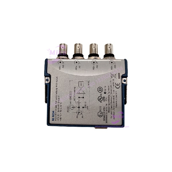
A vibration signature can reveal bearing wear, rotor imbalance, misalignment, or structural resonance long before a machine stops. Capturing those signals correctly requires more than a basic analog input card. The National Instruments NI-9234 is a four-channel C Series sound and vibration input module built for synchronized measurements from compatible accelerometers, microphones, tachometers, and other dynamic signal sensors. Its four analog inputs sample simultaneously, preserving the timing relationships needed for phase analysis and vibration diagnostics.
Each channel combines a 24-bit delta-sigma ADC with analog prefiltering and a sampling-rate-dependent anti-aliasing filter. The maximum internal-timebase sampling rate is 51.2 kS/s per channel, with a ±5 V input range and software-selectable AC/DC coupling. For compatible IEPE sensors, the module supplies approximately 2.1 mA typical excitation current with a maximum compliance voltage of 19 V. That combination suits machinery condition monitoring and acoustic testing—provided the sensor’s bias voltage, signal amplitude, and excitation requirements fall within the module’s electrical limits.
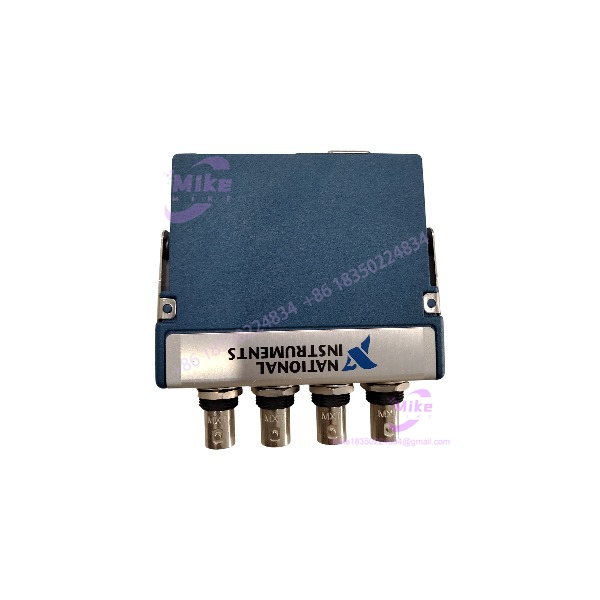
NI-9234
Key Technical Specifications
- Manufacturer: National Instruments
- Model: NI-9234
- Hardware Family: C Series
- Measurement Type: Dynamic analog signal acquisition
- Number of Channels: 4
- Sampling Architecture: Simultaneous sampling across all four channels
- ADC Resolution: 24 bits
- ADC Type: Delta-sigma with analog prefiltering
- Maximum Sampling Rate: 51.2 kS/s per channel with the internal timebase
- External-Timebase Rate Range: Up to 52.734 kS/s, subject to the supported timebase configuration
- Input Voltage Range: ±5 V
- Input Coupling: Software-selectable AC or DC
- IEPE Excitation: Software-selectable, approximately 2.1 mA typical
- IEPE Compliance Voltage: 19 V maximum
- Connector Type: BNC
- TEDS Support: IEEE 1451.4 Class I
- Operating Temperature: −40°C to 70°C
- Power Consumption: 900 mW maximum in active mode
- Ingress Protection: IP40
- Calibration Interval: One year recommended by the manufacturer
The NI-9234 has no channel-to-channel or channel-to-earth-ground isolation. Its specified operating temperature does not override the limits of the chassis, sensor, or wiring.
Application Scenarios & Pain Points
Rotating machinery diagnostics
When a pump or motor develops an abnormal vibration signature, engineers need synchronized measurements to distinguish a bearing fault from imbalance or misalignment. The NI-9234 can acquire four sensor channels at up to 51,200 samples per second per channel, supporting frequency-domain analysis when the sensor bandwidth and test configuration are appropriate.
With versus without simultaneous sampling
- With the NI-9234: Four channels share a simultaneous acquisition architecture, helping preserve relative timing for phase comparisons and multiaxis vibration measurements.
- With nonsimultaneous acquisition: Channel-to-channel timing offsets may complicate phase-sensitive analysis, particularly when comparing vibration signals at higher frequencies.
Acoustic and microphone testing
For sound-pressure measurements, a compatible IEPE microphone or preamplifier can feed the NI-9234 through its BNC interface. Before testing, verify sensor sensitivity, excitation requirements, frequency response, and the complete measurement chain. A 24-bit converter does not automatically guarantee 24-bit effective resolution under real operating noise conditions.
Production-line condition monitoring
A manufacturing line may need vibration data from a motor housing, bearing block, gearbox, and supporting structure. Four synchronized inputs allow those points to be recorded together, helping engineers investigate recurring vibration events without deploying four separate acquisition modules.
Legacy test-bench recovery
If an existing test system fails because of a damaged input module, the NI-9234 may be a suitable replacement candidate. Confirm the chassis model, connector configuration, module variant, driver support, and application timing settings first. A replacement that fits physically but uses an incompatible acquisition configuration can still delay commissioning.
QA & Live Testing SOP
A seller’s description should reflect the condition of the actual unit, not merely the manufacturer’s published capabilities.
- Identity verification: Inspect the model label, serial information, enclosure, and connector configuration. Review available provenance records and packaging where supplied.
- Physical inspection: Check the four BNC connectors for bent contacts, looseness, contamination, or damage. Inspect the enclosure for impact marks and unauthorized repairs.
- Chassis recognition: Install the module in a compatible, correctly powered C Series chassis and confirm that the host recognizes it.
- Channel testing: Apply a known signal to each input in turn. Verify that all four channels return plausible readings and that the acquisition software reports no hardware faults.
- Sampling verification: Configure an appropriate sample rate and confirm that simultaneous acquisition operates as expected.
- IEPE verification: Where suitable test equipment is available, check excitation behavior and confirm that the connected sensor’s bias and signal levels remain within the specified compliance range.
- Signal-quality checks: Inspect for unexpected noise, clipping, intermittent connectors, and channel-to-channel inconsistencies. Use calibrated test equipment if numerical accuracy claims are to be made.
- Packaging: Use ESD-safe packaging and suitable cushioning to protect the module and connectors during transit.
Only report powered testing, calibration, or sensor-compatibility checks as completed when the specific unit has actually passed the corresponding procedure.
Field Engineer’s Pitfall Guide
- ❗ Do not exceed the ±5 V input range. An accelerometer’s output may include a DC bias in addition to the dynamic vibration signal. Check the combined signal and bias against the NI-9234’s IEPE compliance and input-range requirements before enabling excitation.
- ❗ AC coupling is not interchangeable with DC coupling. AC coupling attenuates low-frequency and DC content. The specified AC response reaches −3 dB at approximately 0.5 Hz, so applications requiring static or very-low-frequency measurements need careful configuration. Select coupling based on the measurement objective, not habit.
- ❗ Watch for grounding problems at the BNC connectors. The module’s input channels are not isolated from one another or from earth ground. Follow the manufacturer’s grounding guidance, prevent BNC metal shells from touching each other or the chassis unintentionally, and investigate ground loops before blaming the ADC.
- ❗ Do not assume every C Series chassis supports every configuration. Confirm hardware compatibility, driver support, and synchronization requirements before installation. If several modules must share a sample clock, verify that the chosen chassis and timebase arrangement support the intended synchronization scheme.
Intent-Driven FAQ
Q1: What is the NI-9234 used for?
The NI-9234 acquires sound, vibration, and other dynamic analog signals from compatible sensors. Common applications include accelerometer measurements, machinery diagnostics, acoustic testing, frequency analysis, and condition monitoring.
Q2: How many channels does the NI-9234 have, and are they simultaneous?
It has four analog input channels, and all four are sampled simultaneously. This is useful for phase-sensitive analysis and comparing vibration measurements taken at different points on the same machine.
Q3: What is the maximum sampling rate of the NI-9234?
The maximum rate using the internal timebase is 51.2 kS/s per channel. Supported external-timebase configurations can reach 52.734 kS/s. The selected rate must remain within the device’s supported data-rate constraints.
Q4: Can the NI-9234 power an IEPE accelerometer?
Yes, for compatible IEPE sensors. Excitation is software-selectable, with approximately 2.1 mA typical current and a maximum compliance voltage of 19 V. Confirm the sensor’s operating current, bias voltage, and output amplitude before connecting it.
Q5: Does the NI-9234 support ordinary voltage-output sensors?
Yes, provided the sensor’s output characteristics are compatible with the ±5 V input range and the selected AC/DC coupling configuration. Non-IEPE sensors may require external signal conditioning, depending on their output levels and electrical characteristics.
Q6: Can the NI-9234 replace another C Series analog input module?
Not automatically. Channel count, input range, isolation, connector type, sensor excitation, sampling rate, and software configuration can differ between modules. Check the exact replacement target and application requirements before ordering.
Q7: Is the NI-9234 new surplus, tested, and covered by a warranty?
That depends on the specific seller and unit. Confirm the stated condition, whether the unit has undergone powered testing, what accessories are included, and the duration and scope of any warranty. Request a test report if operational verification is a purchase requirement.
Q8: Does the NI-9234 have electrical isolation between channels?
No. The NI-9234 specifies no channel-to-channel or channel-to-earth-ground isolation. If your application requires isolated measurements, select hardware designed for the relevant isolation requirements rather than attempting to solve the problem through software configuration alone.