

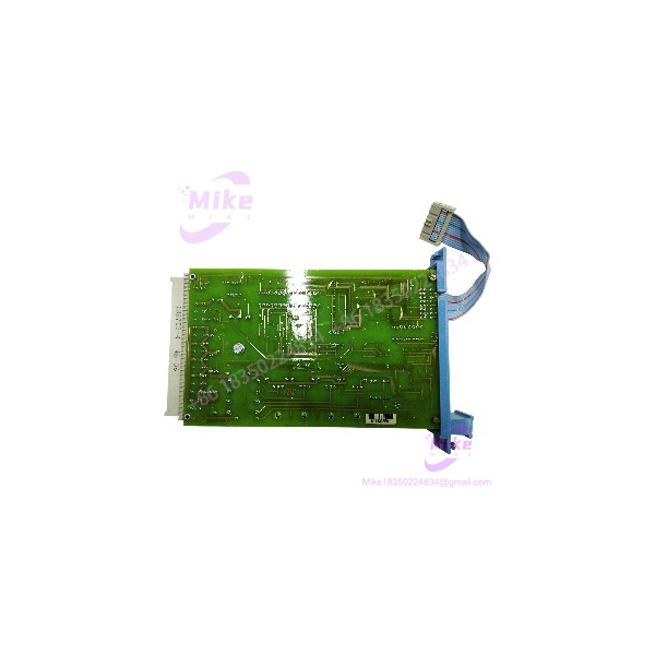
Description
Honeywell FS-SDO-0824 | 8-Channel 24VDC Output
Dynamic Product Introduction
A failed safety output card is not an ordinary PLC I/O replacement. When the affected channels control solenoids, interposing relays, shutdown devices, or other safety-related loads, the replacement has to match the installed Safety Manager architecture—not merely fit the rack.
The Honeywell FS-SDO-0824 is an eight-channel safe digital output module using 24 VDC solid-state source outputs with short-circuit protection. The published maximum channel current is 550 mA, while the hardware documentation specifies a reduction to 350 mA at 70°C. That temperature derating matters in crowded cabinets where ambient conditions are materially higher than the control-room temperature.
For replacement planning, the distinction between FS and FC versions also matters. The FS-SDO-0824 is the non-conformal-coated variant; FC versions are conformal coated. Honeywell documentation identifies V1.1 and later suffix revisions as an improved design with no functional changes, so the exact revision should still be recorded before installation rather than assumed interchangeable from appearance alone.
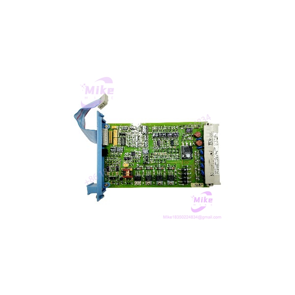
FS-SDO-0824
Key Technical Specifications
- Model: FS-SDO-0824
- Product Type: Safe Digital Output Module
- System: Honeywell Safety Manager
- Output Channels: 8
- Output Type: 24 VDC solid-state source
- Maximum Output Current: 550 mA per channel, subject to temperature derating
- High-Temperature Output Limit: 350 mA at 70°C
- Maximum Lamp Load: 120 mA / 2.9 W
- Maximum Load Capacitance: 1 µF
- Voltage Drop: Less than 2.0 VDC at 500 mA
- Off-State Current: Less than 0.1 mA
- WDG Input Current: 8 mA
- 5 VDC Internal Supply: 25 mA
- 24 VDC Internal Supply: 25 mA
- 24 VDC External Supply: 70 mA, excluding output load
- Mechanical Space: 4 TE × 3 HE, equivalent to 4 HP × 3U
- Key Coding: Module holes A9/C9; chassis large pins A9/C9
- Approvals Listed by Honeywell: CE, TÜV, UL, CSA, FM
The 550 mA figure should not be treated as an unconditional operating value. At elevated temperature, the available output current decreases. This is one of those specifications that can look perfectly acceptable on a procurement sheet while becoming a real commissioning problem inside a hot cabinet.
Global Sourcing & Live-Test SOP
For an FS-SDO-0824 replacement, incoming inspection should begin before the module reaches the test rack.
Inbound Verification
- Record the complete model designation, hardware revision, serial number, and visible manufacturing markings.
- Compare the module identification against the purchase documentation and approved bill of material.
- Inspect the housing, connector area, coding features, PCB condition, and mounting hardware for evidence of refurbishment or mechanical damage.
- Confirm that an FS module has not been substituted with an FC conformal-coated variant without engineering approval.
- Photograph the identification label and physical condition before energization.
The serial number is only one part of the verification process. For safety-system hardware, physical construction and revision information deserve equal attention.
Live Simulation
The preferred procedure is to install the FS-SDO-0824 on an authenticated Honeywell Safety Manager test rack configured for the applicable hardware revision. Do not begin with a production safety loop.
Verify that the module is correctly recognized by the host system and that no unexpected hardware, configuration, or diagnostic faults appear. Each output channel should then be exercised against an appropriate simulated load rather than simply checking whether an indicator changes state.
Diagnostics
A practical test sequence should include:
- Channel-by-channel output activation.
- Output voltage measurement under representative load.
- Short-circuit protection verification using an approved controlled test procedure.
- Off-state measurement where required.
- Field termination and channel mapping verification.
- Watchdog-related diagnostic verification where supported by the test configuration.
- Review of system diagnostic records after repeated output transitions.
A calibrated digital multimeter such as a Fluke-class instrument is appropriate for voltage and continuity checks, but measurement equipment does not replace the Safety Manager diagnostic environment. The important question is whether the complete I/O path behaves correctly.
24-Hour Heat Run
For critical replacement stock, a controlled extended run is preferable to a simple power-on check. Monitor module behavior, output stability, supply voltage, cabinet temperature, and diagnostic status during the heat run.
The documented output-current derating at elevated temperature makes thermal validation particularly relevant.
Final Preparation
Before shipment or installation:
- Record hardware/version information.
- Record serial number and inspection results.
- Seal the module in ESD-safe packaging.
- Protect connectors and keyed interfaces from mechanical impact.
- Include the actual test record with the replacement inventory.
- Preserve the original configuration information supplied by the customer.
For surplus or replacement inventory, “powers on” is not an adequate QC statement. A safety I/O module needs an auditable inspection trail.
The Field Engineer’s Pitfall Guide
❗ Warning 1 — Do not treat FS- and FC- as visually interchangeable.
The FS version is non-conformal coated, while the FC version is conformal coated. That difference can be relevant to environmental qualification and the approved bill of material. Also verify the hardware revision rather than relying only on the base model number. Honeywell identifies V1.1 and later versions as an improved design with no functional changes, but the installed system documentation should remain the authority for a safety-system replacement.
❗ Warning 2 — Do not ignore temperature when calculating output loading.
The headline rating is 550 mA, but Honeywell specifies that output current is limited to 350 mA at 70°C. If a field load is close to the nominal limit, cabinet temperature can turn an apparently acceptable replacement into an operating-margin problem. I’ve seen commissioning teams spend hours chasing a “bad card” when the real issue was thermal loading and an output circuit operating too close to its limit.
❗ Warning 3 — Verify the key coding and termination arrangement before insertion.
The documented coding uses A9/C9 module holes and A9/C9 chassis large pins. Never force a module into a position simply because the front panel appears physically compatible. A mismatched backplane or termination arrangement can turn a routine replacement into a wiring or commissioning incident.
There is another practical issue: do not assume that the field wiring can be moved channel-for-channel without checking the approved drawings. For safety I/O, channel identity is part of the functional design—not just a label on a terminal strip.
Intent-Driven FAQ
Will I lose my logic program if I replace the FS-?
Normally, replacing an I/O module does not mean rewriting the application logic. The real risk is configuration compatibility, channel assignment, diagnostics, and hardware revision. Before removal, document the existing module identity and system diagnostic state so the replacement can be validated against the original configuration.
Can I hot-swap the FS-?
Do not assume hot swapping is permitted merely because the module is physically removable. Follow the installed Safety Manager architecture, approved maintenance procedure, and site safety permit requirements. For a safety-system output card controlling energized equipment, de-energization and proof testing may be mandatory.
Is the FS- still available as an OEM replacement?
Availability varies by revision and inventory position. The practical procurement approach is to specify the complete identification, revision, coating type, and required condition rather than purchasing an item described only as “.”
Can I replace an older V1.0 with a V1.2?
Honeywell’s hardware documentation states that modules with suffix V1.1 or higher incorporate an improved design without functional changes. That supports replacement consideration, but the installed system’s approved hardware list and engineering documentation should still be checked before substitution.
Can the firmware be downgraded if the replacement does not match?
Do not assume that a field-replaceable safety I/O module can be treated like an ordinary PLC CPU firmware package. Hardware revision, system configuration, and approved Safety Manager engineering procedures must be checked first. If a revision mismatch appears, stop and verify the supported configuration rather than forcing a downgrade.
What load can each output actually handle?
The documented maximum is 550 mA, but the output is temperature-dependent and is limited to 350 mA at 70°C. The documentation also specifies a maximum lamp load of 120 mA / 2.9 W and maximum load capacitance of 1 µF. Calculate the actual field load instead of using the 550 mA number as a blanket design allowance.
What should a replacement warranty actually cover?
Get the warranty in writing. At minimum, it should state the covered period, whether the unit is new or surplus, whether DOA coverage applies, and what happens if the module fails the documented incoming or live functional test. For a safety-system replacement, a vague “tested before shipment” statement is not equivalent to a defined replacement warranty.





