

Description
Honeywell FS-CPCHAS-0002 | Safety Manager Controller Chassis
Dynamic Product Introduction
A controller chassis can look like the least complicated item in a safety system—until you have to replace one. The Honeywell FS-CPCHAS-0002 is not merely a metal rack for holding processor cards. It is the physical and electrical framework for the redundant controller arrangement used by the Honeywell Safety Manager system.
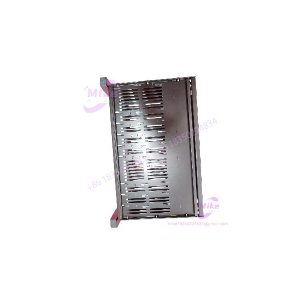
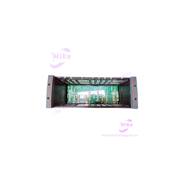
Honeywell’s hardware documentation identifies CPCHAS-0002 as the Controller Chassis for redundant Controller (Safety Manager A.R.T.). The assembly consists of the controller housing and the CPB-0002 controller backplane. The chassis is designed for front loading of the Control Processor modules, while the rear section provides access to the backplane and associated power, communication, watchdog, and safety connections.
That architecture is important during procurement. If a maintenance team needs an FS-CPCHAS-0002, buying a visually similar 19-inch rack does nothing to solve the problem. The backplane, processor mounting arrangement, signal distribution, connectorization, and system-specific mechanical interfaces are part of the actual replacement requirement.
The official hardware reference identifies the chassis as FS-CPCHAS-0002 V1.1 and specifies CE, UL, CSA, TUV, and FM-related approval information in its technical data. A Honeywell Safety Manager certification revision list also identifies FS-CPCHAS-0002 as the Chassis for Control Processor (Advanced Redundancy Technique).
In other words, this is infrastructure for a safety controller—not a generic automation rack.
FS-CPCHAS-0002
Key Technical Specifications
- Manufacturer: Honeywell
- Exact Part Number: FS-
- Hardware Version Referenced: V1.1
- Product Type: Controller chassis
- System: Honeywell Safety Manager
- Architecture: Advanced Redundancy Technique (A.R.T.)
- Primary Function: Housing and interconnection of redundant Control Processor modules
- Backplane: CPB-0002
- Rack Format: 19-inch
- Height: 4 HE / 177 mm / approximately 7 in.
- Width: 482.6 mm / 19 in.
- Depth: 280 mm / 11 in.
- Weight: 5.8 kg / 12.8 lb
- 5V-1 Consumption: 0.05 A
- 5V-2 Consumption: 0.05 A
- Approvals Listed in Hardware Reference: CE, UL, CSA, TUV, FM-related approval information.
- Controller Configuration: Designed for redundant Control Processor installation in the Safety Manager A.R.T. architecture.
Physical Construction
The FS- uses a 19-inch rack architecture with an open front for Control Processor installation. Module guides at the upper and lower portions of the housing help position the processor modules, while quarter-turn fasteners secure the installed modules. The rear section is protected by a hinged cover used for access to the backplane and cable-management area.
Backplane and Signal Distribution
The chassis incorporates the CPB-0002 controller backplane. The rear connection area handles more than simple power distribution. Documentation identifies connections associated with processor power, watchdog signals, communication, and safety-related interfaces.
That is why an FS- replacement should be inspected as an assembly, including the backplane and connectors.
Global Sourcing & Live-Test SOP
Inbound Verification
For an FS-, the receiving inspection should establish identity before any processor modules are installed.
Record:
- Exact part number
- Hardware revision
- Serial/date information where available
- Backplane identification
- Connector condition
- Module guides
- Retaining hardware
- Rear cover condition
- Grounding points
- Signs of corrosion or mechanical damage
The dimensions are a useful secondary identification check: 482.6 × 280 × 177 mm. A unit with substantially different dimensions should not be accepted simply because the seller calls it an FS-.
Backplane Inspection
This is the part worth spending time on.
Inspect:
- Backplane connectors
- Processor card guides
- Power connectors
- Watchdog connections
- Communication connections
- Safety-system interfaces
- Grounding continuity
- Bent or recessed contacts
- Evidence of overheating
- Cracked mounting hardware
A chassis can look almost new externally while having a damaged backplane connector from years of processor-card insertion and removal.
Live Simulation
Unlike a CPU or I/O module, a bare chassis does not have meaningful application logic to execute.
The appropriate test is therefore an assembly-level verification using compatible Safety Manager hardware:
- Inspect the chassis and CPB-0002 backplane.
- Verify grounding and mechanical integrity.
- Check the processor module guides and locking mechanisms.
- Verify power distribution paths.
- Install the correct Control Processor modules.
- Confirm both redundant processor positions seat correctly.
- Verify processor power and watchdog connections.
- Check communication and safety-related connections.
- Confirm normal system diagnostics after controlled energization.
Do not substitute arbitrary processor cards merely to demonstrate that the rack has power. Safety Manager hardware should be tested within the configuration for which it was designed.
Diagnostics
A practical QC report should document:
- Chassis part number
- Revision
- Backplane part number/revision
- Physical dimensions
- Connector condition
- Ground continuity
- Processor-slot condition
- Power-path verification
- Watchdog connection condition
- Communication connector condition
- Successful processor-module installation
- System diagnostic result after controlled power-up
The objective is to prove that the chassis can perform its infrastructure role, not merely that a voltage is present somewhere on the rack.
Final Preparation
Before shipment:
- Photograph the front and rear.
- Photograph the chassis identification label.
- Record backplane identification.
- Protect all exposed connectors.
- Secure removable hardware.
- Use ESD-safe packaging around electronic backplane areas.
- Prevent mechanical impact to the module guides.
- Include the actual inspection/test status.
For a safety-system chassis, traceability should follow the hardware from receiving inspection through installation.
Field Engineer’s Pitfall Guide
❗ Do not confuse with CPCHAS-0001
The two chassis have similar naming, but they serve different controller architectures.
The Honeywell hardware reference specifically identifies as the chassis for the redundant Controller / Safety Manager A.R.T. architecture. The certification documentation separately identifies CPCHAS-0001 as a standard Control Processor chassis.
If the machine BOM calls for FS-, match that exact chassis.
❗ Do not evaluate it as an empty 19-inch rack
A standard 19-inch rack can match the outside dimensions and still be completely useless.
The FS- incorporates the system-specific CPB-0002 backplane, processor guides, power distribution, watchdog connections, communication interfaces, and safety-system interfaces.
In field replacement work, the backplane is the critical part—not the sheet metal.
❗ Check the rear connections before installing expensive processor modules
The rear of the chassis provides access to the power, communication, watchdog, and safety-related wiring. The hardware reference also documents a connector for an Emergency Shut Down system and a 24 V non-safety-related general-purpose input on the chassis assembly.
A damaged or incorrectly wired rear connector can turn an apparently good chassis into a commissioning failure.
Intent-Driven FAQ
What is the Honeywell FS-?
The is a Honeywell Safety Manager controller chassis designed for redundant Control Processor installation using the Advanced Redundancy Technique (A.R.T.). It includes the controller housing and CPB-0002 backplane.
What are the dimensions of FS-?
The documented dimensions are 177 mm high × 482.6 mm wide × 280 mm deep, equivalent to 4 HE × 19 in. × 11 in. The documented weight is 5.8 kg / 12.8 lb.
Does FS- support redundant processors?
Yes. This is specifically the purpose of the architecture. Honeywell’s certification documentation describes it as the Chassis for Control Processor (Advanced Redundancy Technique), and the hardware reference describes the chassis as the controller housing for the Safety Manager redundant-controller arrangement.
What backplane does FS- use?
The controller chassis incorporates the controller backplane. The backplane provides the electrical interconnection required between the controller modules and chassis infrastructure.





