

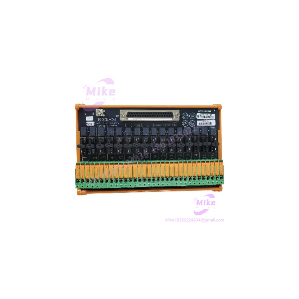
Description
Honeywell FC-TDIO51 | 16-Channel Safety Manager FTA
Dynamic Product Introduction
The biggest procurement mistake with FC-TDIO51 is calling it a 16-channel digital I/O module. It isn’t. The actual I/O processing is performed by the FC-PDIO01; FC-TDIO51 is the field termination hardware that provides the physical interface between that Safety Manager SC I/O architecture and the external field wiring.
Honeywell’s supported-hardware documentation makes this relationship explicit: FC-PDIO01 → FC-TDIO11 / FC-TDIO51 / FC-TDIO52, with FC-TDIO51 identified as the 16-channel, 24 VDC, knife/EOL, left-hand safety FTA.
That distinction matters when sourcing a replacement. A technician searching only for “16-channel 24 VDC Safety Manager I/O” can easily end up with the wrong hardware. FC-TDIO51 has to be matched to the appropriate FC-PDIO01 installation, physical termination arrangement, channel allocation, and system architecture.
The Safety Manager SC platform is Honeywell’s third-generation safety platform, using an S300 processor and Safety Digital I/O architecture. FC- belongs to that SC-specific field interface ecosystem rather than the older Safety Manager local-I/O FTA families.
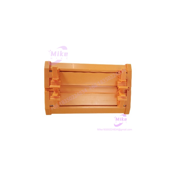
FC-TDIO51
Key Technical Specifications
- Manufacturer: Honeywell
- Model:
- Product Type: Safety Field Termination Assembly (FTA)
- System: Honeywell Safety Manager SC
- Associated I/O Module: FC-PDIO01
- I/O Type: Safety Digital I/O
- Nominal Field Voltage: 24 VDC
- Channel Capacity: 16 channels
- Termination Type: Knife / EOL
- Orientation: Left-hand (L)
- Function: Field wiring termination/interface
- Controller/I/O Family: Safety Manager SC / S300 architecture
- Associated Redundant FTA: FC-TDIO11 is the dedicated redundant PDIO FTA in the documented architecture
- Alternative Orientation: FC-TDIO52 is documented as the corresponding right-hand (R) FTA
- Safety System: Honeywell Safety Manager SC
Honeywell’s R210.2 software documentation specifically identifies FC- and FC-TDIO52 as the two 16-channel 24 VDC knife/EOL FTAs associated with FC-PDIO01.
What FC- Does — and Does Not Do
Think of the architecture as:
Safety application → FC-SCNT01 → FC-PDIO01 → FC- → field wiring
The FC- is on the field termination side. It does not replace the FC- processor/I/O electronics.
This is why a listing that describes FC- as a “digital input/output module” is technically misleading. The correct procurement classification is Safety Field Termination Assembly.
Global Sourcing & Live-Test SOP
1. Inbound Verification
Receiving inspection should begin with the physical identity rather than an electrical bench test.
Record:
- Exact marking
- Hardware revision, if marked
- Serial/traceability information
- Connector condition
- Knife-terminal condition
- EOL/termination components
- Housing and mounting condition
- Signs of corrosion, contamination, or mechanical damage
- Evidence of previous field installation
Confirm that the physical unit is actually , not FC-TDIO52.
That distinction is not cosmetic. Honeywell identifies FC- as the left-hand FTA and FC-TDIO52 as the right-hand version.
2. Configuration Verification
Before installation, compare the target system’s bill of material against:
- FC- module
- FC- FTA
- Required redundant/non-redundant architecture
- Left/right termination position
- Field channel assignment
- 24 VDC field wiring
- End-of-line arrangement
- Cabinet mechanical layout
The FTA should be treated as part of the qualified I/O assembly rather than as an interchangeable terminal block.
3. Live Simulation
A proper acceptance test should use an authentic Honeywell Safety Manager SC test configuration containing the appropriate FC- hardware.
Verify:
- FC- recognizes the connected termination architecture.
- Field wiring is landed on the correct channels.
- Each representative field circuit produces the expected input/output state.
- EOL/line-monitoring behavior is consistent with the configured circuit.
- Diagnostic status is normal.
- Channel mapping agrees with the Safety Builder application.
- Redundant operation is verified when the installation uses the redundant architecture.
Honeywell’s documentation identifies FC- as part of the supported FC- hardware arrangement in Safety Manager SC R210.2.
4. Diagnostics and Final Preparation
Capture:
- FC- identification
- FC- identification
- Controller/Safety Manager SC release
- Channel assignment
- Field-wiring verification
- EOL configuration
- Diagnostic results
- Redundancy test results where applicable
After acceptance testing:
- Photograph the FTA identification.
- Record the exact configuration.
- Protect the terminals against contamination.
- Use ESD-safe packaging where appropriate.
- Keep the FTA and its associated FC- configuration traceable in inventory.
For a safety-system spare, the useful record is not simply “FTA tested.” It is which FTA, paired with which I/O module, in which system configuration.
Field Engineer’s Pitfall Guide
❗ 1. FC- Is Not FC-
This is the first thing to get right.
FC- is the Safety Digital I/O module. FC- is its field termination assembly.
Honeywell’s R210.2 documentation explicitly lists FC- followed by its associated FC-TDIO11, FC-, and FC-TDIO52 termination hardware.
Buying FC- when the failed component is actually FC- will not solve the I/O-module problem.
❗ 2. Check Left vs. Right Orientation
FC- is documented as the 16-channel, 24 VDC, knife/EOL, left-hand FTA.
FC- is the corresponding right-hand version.
A replacement can therefore be electrically related to the same I/O family and still be mechanically wrong for the intended cabinet position.
This is exactly the sort of detail that causes a supposedly simple spare-parts replacement to stop at the installation stage.
❗ 3. Do Not Treat the FTA as a Generic Terminal Block
The field termination assembly is part of the Safety Manager SC I/O architecture.
The system’s channel mapping, termination method, EOL arrangement, and associated FC- module all matter. Replacing it with a generic terminal assembly may provide physical connections while completely bypassing the intended qualified architecture.
Intent-Driven FAQ
What is Honeywell FC-?
FC- is a Safety Manager SC Field Termination Assembly (FTA) used with the FC- Safety Digital I/O module. Honeywell identifies it as a 24 VDC, 16-channel, knife/EOL, left-hand safety FTA.
Is FC- a digital input/output module?
No. It is a field termination assembly. The FC- is the associated Safety Digital I/O module.
How many channels does FC- support?
Honeywell’s R210.2 documentation specifies 16 channels for FC-.
Is FC- designed for 24 VDC?
Yes. Honeywell identifies the FC- as a 24 VDC, 16-channel Safety Manager SC safety FTA.
What does “L” mean for FC-?
The Honeywell description identifies FC- as the left-hand (L) version. FC- is documented as the corresponding right-hand (R) version.
What is the difference between FC- and FC-?
They are the left/right variants of the Safety Manager SC FC- termination arrangement:
- 16-channel, 24 VDC, knife/EOL, left
- 16-channel, 24 VDC, knife/EOL, right
Do not substitute one based solely on the shared channel count.





