


Description
Honeywell 51304485-100 | Digital Input Module, New Surplus
Architect’s Product Breakdown
The Honeywell 51304485-100 operates as a high-capacity digital input card engineered for the TDC 3000 distributed control ecosystem. Its core purpose is gathering thirty-two discrete field states—including pump run signals, valve status contacts, and safety interlocks—and converting them into clean, optically isolated logic levels for the system backplane. This optical barrier is vital for protecting sensitive central processor nodes from high-voltage transient spikes originating in long cable runs out in the plant.
Deploying this module requires meticulous attention to field termination assembly (FTA) cable mapping and loop power compatibility. Maintenance personnel must verify that sinking or sourcing configurations match the existing field instrumentation layout to prevent unread inputs or ghost states. Ensuring that the module is firmly seated into its chassis slot is critical, as a loose connection will induce intermittent communication timeouts across all thirty-two channels.
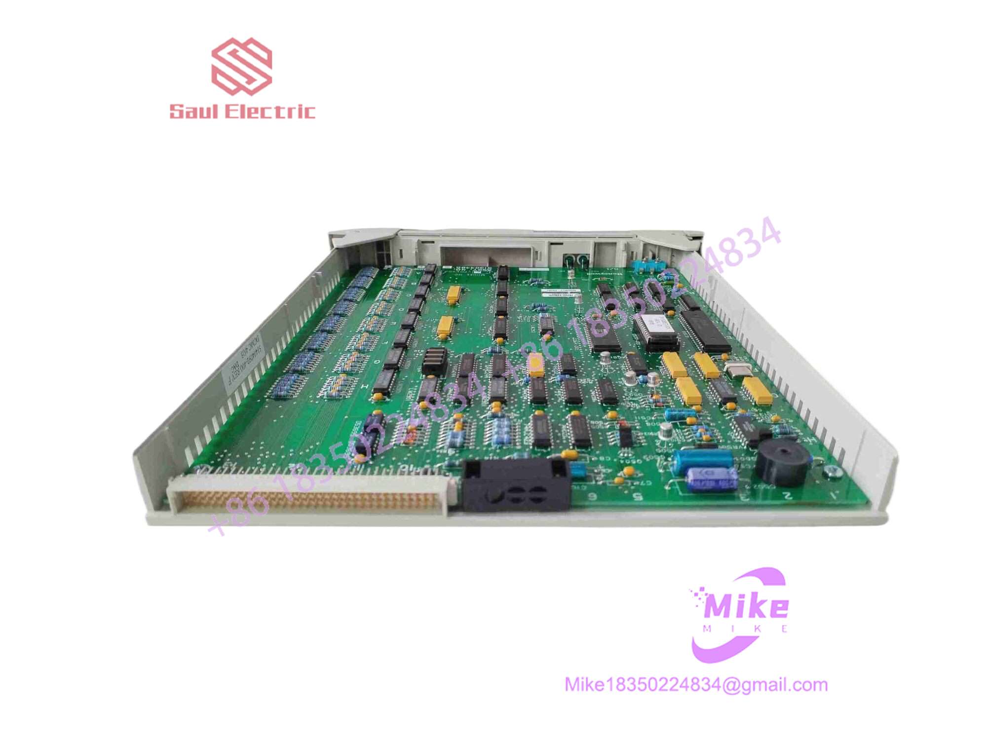
51304485-100
Key Technical Specifications
| Parameter | Specification |
| Manufacturer | Honeywell |
| Part Number | 51304485-100 |
| Module Type | High-Density Digital Input Module |
| Compatible Architecture | TDC 3000 / Experion PKS |
| Channel Count | 32 Discrete Inputs |
| Mounting Type | Chassis Slot / Backplane Connection |
| Operating Temperature | 0°C to +60°C |
| Storage Temperature | -40°C to +85°C |
| Relative Humidity | 5% to 95% non-condensing |
Field Engineer’s Pitfall Guide (Unique Value)
- FTA Harness Mismatches: Swapping this card while crossing over multi-pin pre-fabricated cable harnesses on the back edge will completely scramble channel logic. Always cross-reference cable tags against system configuration drawings before tightening retention screws.
- Common Mode Voltage Surges: Failing to verify that the field power supply shares a proper reference ground with the control cabinet can induce ground potential differences, frying the internal optical isolation barriers during lightning storms or heavy inductive switching.
- Static Discharge Vulnerability: Handling the exposed edge connector pins without a grounded wrist strap in dry plant environments can ruin internal logic gates. I once watched an instrument tech plug in a replacement module straight out of a cold cardboard box without ESD protection, immediately locking up the node bus.
QA & Testing SOP (Transparency)
- Visual & Origin Verification: Units are inspected under magnification for original OEM stamps, uncompromised solder traces, and clean multi-pin edge connectors.
- Test Bench Simulation: The module is inserted into a live test rack configured with a matching FTA simulator to verify backplane handshakes and module health registers.
- Channel State Validation: Automated test rigs cycle logic states across all 32 channels simultaneously, checking optical isolation integrity, response time, and LED indicator status.
- Anti-Static Packaging: Post-testing, units are sealed inside heavy-duty static-shielding bags with high-density protective foam inserts.
Technical FAQ
- Can I hot-swap this digital input module while the process is running? No. Always de-energize the rack and isolate field power sources before extracting or inserting this card to prevent backplane arcing and bus corruption.
- Does this module require local configuration switches? Most configuration parameters are handled via software system generation, but always verify historical jumper settings if migrating from an older hardware revision.
- What indicates a failing input channel during runtime? A channel that remains locked in a static state regardless of field switch movement typically points to an optical coupler failure on that specific input circuit.
- What warranty is provided with a surplus unit? Units carry a standard 12-month replacement warranty backed by comprehensive multi-channel bench testing.





