

Description
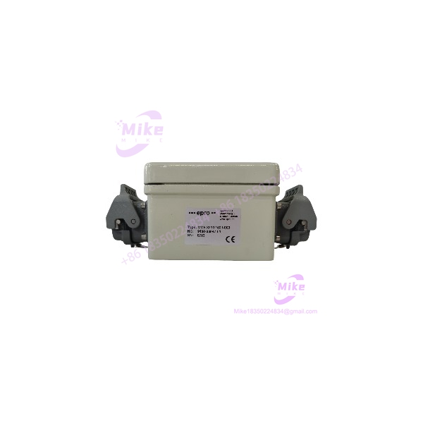
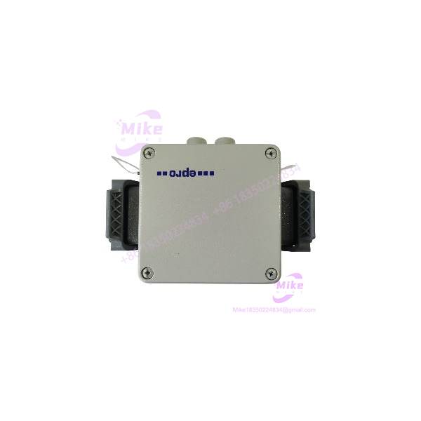
EPRO MMS3210021-000 | Shaft Displacement Transmitter
Product Introduction
For rotating machinery where shaft position is a protection variable rather than simply a diagnostic trend, the signal-conditioning stage has to match the sensor architecture, measurement range, and downstream protection system. The EPRO MMS3210021-000 belongs to the MMS3000 machinery-monitoring family and is configured for two-channel shaft displacement/position measurement.
Its primary role is to process non-contact eddy-current probe signals and provide standardized monitoring outputs for control, condition-monitoring, alarm, or machinery-protection architectures. The two-channel arrangement allows two measurement points to be handled independently — useful when monitoring axial position, radial shaft displacement, or related shaft-motion parameters on critical rotating equipment.
This makes the MMS3210021-000 relevant to legacy EPRO/Emerson machinery-monitoring installations where maintaining the original measurement chain is preferable to redesigning the entire protection interface.
MMS3210/020-020
Key Technical Specifications
- Model: MMS3210021-000
- Standardized OEM format: MMS3210/021-000
- Manufacturer: EPRO / Emerson
- System family: MMS3000
- Device category: Dual-channel shaft displacement transmitter
- Measurement principle: Non-contact eddy-current sensing
- Measurement channels: 2 independent channels
- Compatible sensor family: EPRO PR6422 / PR6423 / PR6424 / PR6425 / PR6426 family, subject to exact configuration
- Analog outputs: 2 × 0/4–20 mA
- Supply class: 24 VDC
- Signal conditioning: Integrated sensor signal processing
- Typical measurement variables: Shaft displacement, shaft position, axial position, and related relative shaft-motion measurements
- Monitoring platform: EPRO MMS3000
- Installation: Machinery-monitoring / field transmitter application
- Application standard: Published product references associate the MMS3210/021-000 with API 670 machinery-monitoring applications
- Configuration dependency: Sensor type, measurement range, output scaling, and system interface should be verified from the installed unit documentation before commissioning
Published references identify the MMS3210/021-000 as a dual shaft displacement transmitter and specify PR6422–PR6426 eddy-current probes and two 0/4–20 mA outputs. Because the available online documentation is primarily distributor-supplied rather than an OEM datasheet, configuration-dependent values should be confirmed against the unit’s nameplate/manual before a like-for-like replacement is approved.
Application Scenarios & Pain Points
Steam and Gas Turbines
The MMS3210021-000 can be used within shaft-monitoring architectures where axial or radial shaft movement must be converted into a control-system-compatible signal.
Procurement concern: A replacement transmitter is not interchangeable merely because it belongs to the MMS3210 family. The 021-000 suffix matters because different MMS3210 variants serve different measurement functions.
Centrifugal Compressors
Two independent displacement channels can support monitoring at separate shaft measurement locations.
Typical engineering requirement: preserve the existing probe type, mechanical gap, scaling, and receiving-system signal range rather than changing several elements of the measurement chain simultaneously.
Pumps and Large Motor-Driven Machinery
Legacy machinery-monitoring installations may depend on an EPRO transmitter that is no longer routinely supported through the original plant procurement channel.
The MMS3210021-000 can therefore be considered when restoring an existing MMS3000 measurement loop without redesigning the complete monitoring architecture.
Thrust and Axial-Position Monitoring
Where the installed arrangement measures axial shaft movement, the transmitter’s two-channel displacement architecture can provide the signal-conditioning stage between the eddy-current probes and the plant’s monitoring/protection system.
Important: mechanical probe installation and measurement range remain application-specific.
Legacy MMS3000 Replacement
For an obsolete rack or field installation, the practical question is not simply “Does the connector fit?”
The replacement should be checked against:
- Existing PR642x probe configuration
- Probe/pre-amplifier arrangement
- Measurement range
- 0–20 mA vs. 4–20 mA signal configuration
- Alarm/protection interface
- Supply arrangement
- Existing MMS3000 architecture
- Wiring and terminal assignment
QA & Live Testing SOP
For a procurement-grade replacement, the following verification sequence is recommended before shipment or field installation.
1. Identity verification
Confirm the physical nameplate reads or the corresponding MMS3210/021-000 designation. Photograph the label, terminal area, and housing condition for the maintenance record.
2. Physical inspection
Check for:
- Cracked housing
- Bent or damaged terminals
- Corrosion
- Missing covers
- Evidence of moisture ingress
- Altered labels
- Damaged adjustment hardware
3. Sensor-interface verification
Confirm the intended PR642x sensor configuration against the plant’s existing installation documentation. Do not assume that every PR642x probe is interchangeable without checking measuring range and associated electronics.
4. Electrical bench test
Using an appropriate current-limited 24 VDC laboratory supply and suitable test equipment, verify that the transmitter powers correctly and that both channels respond to an appropriate simulated or controlled input.
5. Output verification
Check both analog channels across their configured operating range. Record:
- Channel 1 output
- Channel 2 output
- Zero/reference point
- Span response
- Stability
- Fault indication behavior
6. Documentation
Record the exact model, suffix, serial number, measured outputs, test equipment, test date, and final inspection status.
7. Packaging
Use ESD-safe handling and protective packaging. Terminal areas should be mechanically protected so that transportation cannot introduce connector or wiring damage.
This is a recommended QA procedure, not a claim that testing has already been performed on a particular unit.
Field Engineer’s Pitfall Guide
❗ Do not substitute an variant solely because the base model matches.
The family contains multiple configurations, including /010-000, /011-000, /020-020, and /021-000 variants. Their functions are not necessarily interchangeable.
❗ Verify the sensor chain before connecting power.
The is associated with EPRO PR642x eddy-current sensing. Probe type, measuring range, and associated signal-conditioning hardware need to agree with the transmitter configuration.
❗ Do not assume 0–20 mA and 4–20 mA are equivalent at the protection-system interface.
The receiving PLC, DCS, vibration-monitoring rack, or shutdown system may use the live-zero behavior for fault detection. Confirm the installed configuration before changing signal scaling.
❗ Check the complete loop, not just the transmitter.
A technically correct transmitter can still produce incorrect measurements if probe gap, extension cable, preamplifier configuration, polarity, or receiving-channel scaling is wrong.
❗ Verify the exact suffix before approving a replacement.
Online reseller catalogs sometimes shorten the designation to or , while the more complete product designation is . The physical nameplate should control the procurement decision.
Intent-Driven FAQ
Is the same product as /021-000?
Yes, the available product references identify as the corresponding EPRO product designation. The hyphenated inventory form is commonly used in part-number databases and listings.
What does the measure?
It is intended for dual-channel shaft displacement / position monitoring using non-contact eddy-current sensing. Depending on the machine installation, this can relate to shaft displacement or axial-position measurements.
Which sensors are compatible?
Available references specify EPRO PR6422, PR6423, PR6424, PR6425, and PR6426 eddy-current probe families. Exact compatibility still depends on the probe variant, measuring range, and installed signal-conditioning arrangement.
Does provide 4–20 mA outputs?
Published technical information specifies two 0/4–20 mA analog outputs. The actual output configuration should be confirmed against the installed unit and project documentation before commissioning.
Can I replace an /020-020 with ?
Do not treat them as automatic substitutes. Both belong to the family, but the suffix identifies a different configuration. Available references associate /020-020 and /021-000 with different monitoring applications, so the plant’s measurement function must be verified first.
Is suitable for a legacy system?
It is identified as an -family transmitter, making it relevant to legacy EPRO/Emerson machinery-monitoring installations. Final compatibility requires checking the existing sensor loop, power arrangement, output configuration, and receiving protection/monitoring hardware.
What should I verify before purchasing?
Provide the supplier with the complete part number, nameplate photograph, existing sensor model, and application function. For critical machinery, also verify the existing wiring and output scaling. Those details are more useful than matching the prefix alone.





