

Description
Emerson PR6426/010-140 | 32mm Non-Contact Eddy Current Sensor
Dynamic Product Introduction
Plant engineers dealing with large industrial steam turbines know that improper shaft sensing configurations lead to unexpected maintenance shutdowns and costly false trips. Standard 8mm probes often fail to capture wide-span thermal expansions on massive rotors, leaving critical bearings vulnerable to unmonitored wear. The Emerson PR6426/010-140 addresses this engineering challenge head-on by utilizing a robust 32mm sensor head and an unthreaded 80 mm x 40 mm mounting plate designed for secure bracket installation right inside heavy turbine casings.
Engineers specifying the PR6426/010-140 gain an active 8 mm linear measurement span with a 2 V/mm sensitivity slope, providing high-resolution position feedback even at shaft speeds up to 2,500 m/s. The 4-meter integrated cable features a heavy-duty stainless steel protective armor jacket and bare open-end wire terminations. This raw-wire layout lets technicians land the probe directly onto terminal blocks inside signal conversion boxes without dealing with intermediate connector bulk, ensuring a clean and reliable signal loop for your AMS 6500 monitoring architecture.
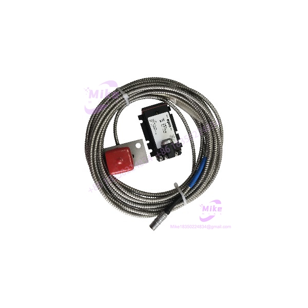
PR6426/010-140+CON021
Key Technical Specifications
- Sensor Head Outer Diameter: 32 mm
- Mechanical Body Style: Unthreaded sleeve with 80 mm x 40 mm rectangular mounting plate
- Linear Measuring Range: 8 mm nominal span (extendable up to 24 mm with specialized signal conditioners)
- Sensitivity & Linearity: 2 V/mm (50.8 mV/mil) with linearity error ≤ ±1.5% max
- Nominal Air Gap Center: 5.5 mm (0.22 inches)
- Frequency Response: Static DC up to 20 kHz (-3dB cutoff point)
- Target Shaft Speed Limit: Up to 2,500 m/s (98,425 ips)
- Calibrated Target Material: Ferromagnetic steel (42 Cr Mo 4 standard)
- Cable Build & Length: 4 meters total length, flexible stainless armor over PTFE insulation, open-end stripped wires
- Temperature Rating: Operating range from -35°C to +175°C (-31°F to +347°F); transient excursions to +200°C (<4 hours)
- Sealing & Tip Pressure: IP67 sealed PEEK tip rated for head pressures up to 6,500 hPa (94 psi)
- Hazardous Area Approvals: ATEX / IECEx / CSA Intrinsic Safety (iA) certifications
Global Sourcing & Live-Test SOP (Transparency Core)
Sourcing replacement instrumentation for critical turbine supervision requires rigorous validation before equipment enters a live plant environment. Every PR6426/010-140 inventory unit undergoes a strict multi-point quality control procedure:
- Inbound Verification: Serial numbers stamped on the mounting plate are checked against factory distribution records. We inspect the 32mm PEEK sensor face for micro-abrasions, examine the stainless steel armor swage joints for mechanical fatigue, and check open wire ends for oxidation.
- Live Simulation: The PR6426/010-140 probe head is clamped onto a calibrated micrometer test fixture aligned with a 42 Cr Mo 4 target disc. The open-end leads are wired directly into a bench-mounted CON021 signal converter powered by a regulated 24 VDC source.
- Diagnostics: The air gap is zeroed and stepped across the full 8 mm span in 0.5 mm increments. Output voltage is captured using a Fluke 87V meter to confirm that sensitivity holds dead-steady at 2 V/mm within the ≤ ±1.5% tolerance threshold. An oscilloscope checks the 4-meter cable run for noise suppression and ripple limits up to 20 kHz.
- Environmental & Electrical Soak: Insulation resistance testing between the outer armor and inner conductors is executed at 500 VDC, ensuring a clean threshold exceeding 100 MΩ.
- Final Prep: Baseline calibration curves are logged, the bare wire ends are sealed in protective shrink tubing, and the entire PR6426/010-140 assembly is packed in an anti-static moisture-barrier bag.
The Field Engineer’s Pitfall Guide
❗ Altering the 4-Meter Factory Cable Length: Never cut or lengthen the 4-meter armored cable on the PR6426/010-140 in the field. The probe, cable insulation, and driver circuit form a tuned LC resonant circuit where total loop inductance and capacitance govern calibration. Shortening or splicing the cable shifts the operating frequency, causing severe measurement drift and invalid axial position data at the control room rack.
❗ Neglecting Mounting Plate Side-Wall Clearance: Because the PR6426/010-140 features a large 32mm head diameter, its high-frequency electromagnetic field projects widely around the sensor tip. Installing this probe inside a restrictive bore or failing to maintain an 80 mm minimum radial clearance from adjacent steel casing walls causes side-wall loading—a common field error that consumes part of your 5.5 mm nominal air gap and creates false DC voltage offsets.
❗ Improper Grounding of Open-End Armor Shields: The PR6426/010-140 features open-end bare wires that include an outer shield drain wire. In field installations, terminating this drain wire at both ends (the junction box and the signal converter) creates a massive ground loop. Ground the shield exclusively at the converter rack end to prevent 60 Hz electrical noise from corrupting your low-level vibration signals.
Intent-Driven FAQ
Q: What do the numerical digits in the PR6426/010-140 part number represent? The model code defines the physical configuration: /010 indicates the unthreaded mounting plate body style (80 mm x 40 mm plate) without threaded sleeves. The -140 suffix breaks down as follows: armored cable (1), a total length of 4 meters (4), and open-end stripped wire terminations (0).
Q: Can I connect the open-end wires of the PR6426/010-140 directly into a standard PLC analog input? No. The PR6426/010-140 is a raw eddy current transducer that requires high-frequency oscillator-demodulator circuitry. The open-end leads must land on an approved signal converter (such as a CON011, CON021, or CON041) or a dedicated AMS 6500 front-end card, which converts the raw signal into a standardized -2 to -18 VDC or 4-20 mA output for your DCS.
Q: What is the primary operational difference between the PR6426/010-140 and shorter 2-meter probe models? The difference lies entirely in the cable length and termination layout. The PR6426/010-140 features a 4-meter armored cable with bare open-end wires, designed for direct terminal block hookups inside junction boxes located further away from the signal converter rack. It shares the exact same 32mm sensor head performance and 8 mm linear range as shorter variants.
Q: How can I field-test a PR6426/010-140 probe for internal coil failure during an outage? Disconnect the probe leads from the signal converter or junction box terminals. Use a digital multimeter set to resistance (Ohms) to measure across the core signal wire and the inner return shield. A healthy PR6426/010-140 coil will show a low continuous resistance value (typically under 10 ohms). An open circuit (infinite ohms) indicates a sheared internal winding or severe mechanical cable damage.
Q: Does replacing an existing PR6426/010-140 require recalibrating the monitoring rack? When swapping a PR6426/010-140 with an identical part number while keeping the same signal converter and cable run, full electronic recalibration is generally unnecessary. However, you must perform a static gap check: verify that the DC voltage at the converter test points matches the baseline gap setting (typically around -10 VDC at the 5.5 mm mid-gap position) when the machine is stopped at ambient temperature.





