


Description
B&R 7CP476-010.9 | SYSTEM 2003 CPU Module, New Surplus
Architect’s Product Breakdown
The B&R 7CP476-010.9 is an expanded CPU variant within the legacy SYSTEM 2003 product line. Engineered for applications requiring dedicated memory expansion or removable project backing, this model takes the core processing architecture of the standard CP476 and pairs it with a PCMCIA card slot (left-hand bay). It packages 750 KB of zero-wait-state SRAM for execution variables alongside 1.5 MB of embedded FlashPROM for application code retention.
Equipped with an integrated 24 VDC power supply delivering up to 12.15 W directly to the backplane, the module eliminates the requirement for a separate power supply card on smaller rack setups. Serial communication for programming or HMI uplink is handled via an RS232 interface, while machine-level fieldbus coordination is executed through an electrically isolated CAN bus port. The front fascia also incorporates four screw-in expansion slots for modular serial or fieldbus interface cards.
The primary operational advantage of the -010.9 designation is its PCMCIA slot, which accepts external SRAM or Flash memory cards (e.g., B&R 0MC series). This allows maintenance teams to store extensive recipe libraries, archive data logs locally, or execute field program updates simply by swapping PCMCIA media—avoiding the need to lug a laptop into hazardous or cramped machine environments.
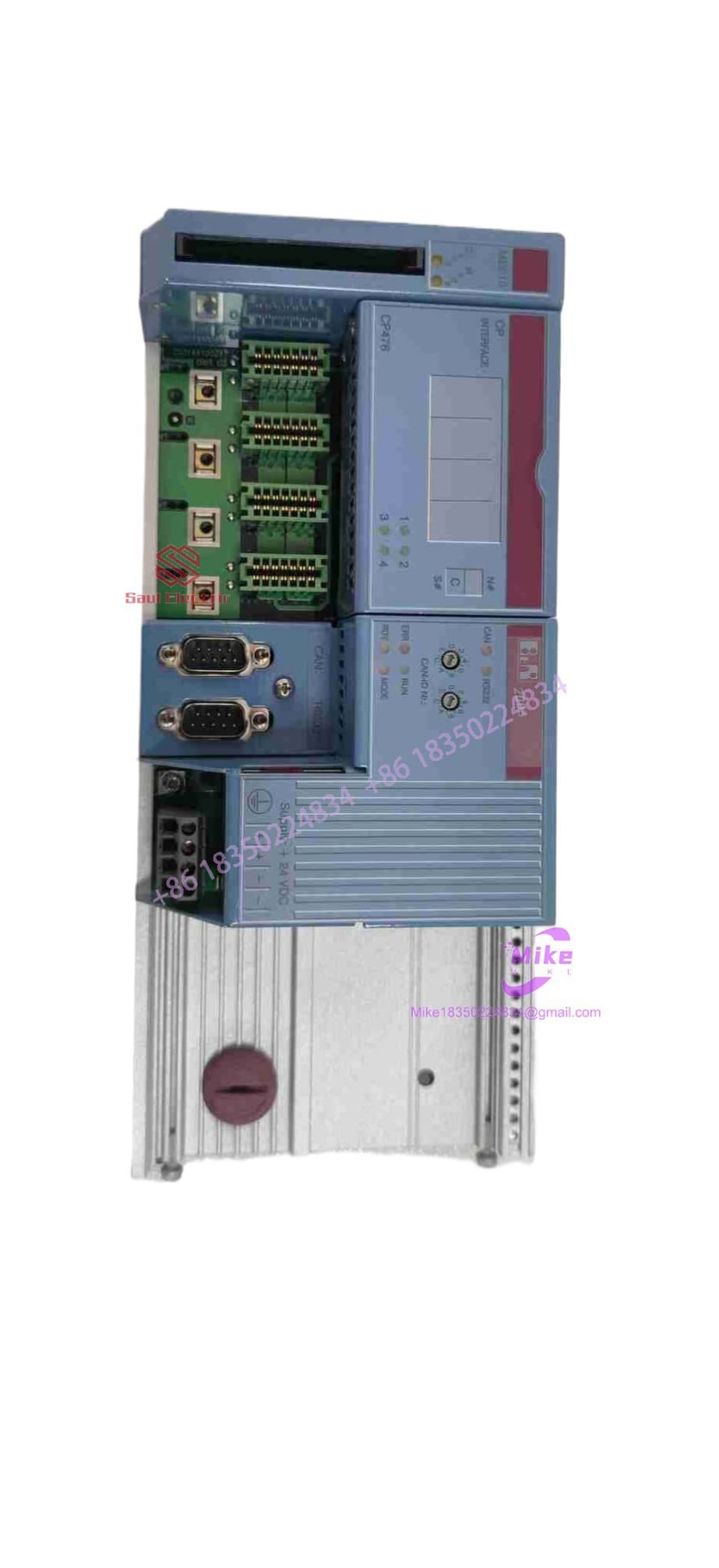
7CP476-010.9
Key Technical Specifications
| Parameter | Specification |
| Input Voltage | 24 VDC (-15% / +20%) |
| Internal Power Supply Output | 12.15 W max. system backplane power |
| SRAM Memory (Onboard) | 750 KB (Battery-buffered) |
| Flash Memory (Onboard) | 1.5 MB FlashPROM |
| Memory Expansion Slot | 1x PCMCIA Card Slot (Supports SRAM / Flash cards) |
| Serial Interface | 1x RS232 |
| Fieldbus Interface | 1x CAN interface (Electrically isolated) |
| Expansion Slots | 4x slots for screw-in interface modules |
| Backup Battery Type | 3V / 950 mAh Lithium button cell (e.g., B&R 4A0006.00-000 / 0AC201.91) |
| Dimensions & Weight | 160 x 99 x 44 mm |
| Certifications | CE, cULus HazLoc Class I Div 2 Groups ABCD |
| Operating Temperature | 0°C to +60°C |
Field Engineer’s Pitfall Guide
WARNING: PCMCIA Card Hot-Swapping Delivers Data Corruption
The PCMCIA memory card bay on the left of the 7CP476-010.9 is not hot-swappable during active PLC scan execution. Inserting or ejecting an SRAM or Flash card while the CPU is in RUN mode can spike the memory bus, freeze logic execution, or permanently corrupt the card’s file allocation table. Always toggle the CPU switch to STOP or isolate 24 VDC power before seating or ejecting memory cards.
WARNING: SRAM Battery Decay and PCMCIA Memory Retention
The onboard 750 KB SRAM and any inserted PCMCIA SRAM cards rely on 3V lithium power to retain dynamic registers during plant outages. PCMCIA SRAM cards often have their own internal secondary coin cell in addition to the CPU main battery. If you replace the CPU battery but ignore the expired battery inside the PCMCIA card itself, your custom recipe tables will vanish the moment main power drops. Replace both batteries during scheduled routine maintenance.
WARNING: Rotary CAN Switch Address Mismatches
Physical node addressing on the CAN interface is set via hardware rotary switches on the module faceplate. Replacing a blown CPU with a spare straight out of the box without matching the two rotary hex/decimal dials will prevent the CAN bus from establishing a handshake, causing downstream I/O racks to drop off the network immediately.
QA & Testing SOP
- Visual & Structural Inspection:
- Verify original OEM serial label, hardware revision indices (e.g., Rev. G0), and housing integrity.
- Check PCMCIA slot pins for bent, shorted, or recessed contacts.
- Inspect backplane connector pins, locking levers, and screw-in module threads.
- Electrical & Power Bench Tests:
- Connect to a regulated 24 VDC laboratory power supply.
- Measure backplane output rail voltages under a dummy 10 W load to verify internal power supply regulation.
- Test lithium battery holder tension and verify incoming cell terminal potential under load.
- Bench Test Environment:
- Slot module onto a standard B&R SYSTEM 2003 base plate.
- Establish an RS232 online session via B&R Automation Studio.
- Run memory diagnostic routines across both onboard SRAM (750 KB), FlashPROM (1.5 MB), and test PCMCIA expansion media.
- I/O & Network Handshake Verification:
- Loop-test the isolated CAN port using a PC CAN analyzer; record TX/RX frame stability across varying baud rates.
- Execute a 24-hour heat-chamber burn-in test at 50°C to verify cyclic logic stability and thermal dissipation performance.
- Final Logistics Preparation:
- Wipe volatile memory back to default industrial base state.
- Package module in custom-fit anti-static ESD shielding with desiccant packs before boxing.
Technical FAQ
What is the difference between the standard 7CP476.60-1 and the 7CP476-010.9?
The primary difference is the addition of the PCMCIA card expansion bay on the left side of the 7CP476-010.9. While both modules share core processing capabilities, internal memory (750 KB SRAM / 1.5 MB FlashPROM), and backplane power outputs, the -010.9 variant allows field engineers to plug in external memory cards for extended data storage or rapid offline project updates.
Can I run this processor if the backup battery dies completely?
Yes, but with strict operational limits. The CPU will boot and execute the base application code stored in the non-volatile 1.5 MB FlashPROM. However, all retentive variables, counter values, dynamic setpoints, and runtime recipe data stored in the 750 KB SRAM will reset to default or zero values on every power cycle.
Is a PCMCIA card mandatory to boot and run the CPU?
No. The PCMCIA slot is an optional expansion feature. The 7CP476-010.9 contains 1.5 MB of onboard FlashPROM and 750 KB of onboard SRAM, which is fully sufficient to boot, store, and execute user programs without any PCMCIA card installed.
How do I connect my PC to the 7CP476-010.9 for programming?
You must use a standard B&R RS232 serial cable connected to the CPU’s front RS232 interface. On the software side, you need B&R Automation Studio configured with the appropriate System 2003 target hardware definitions and matching Automation Runtime (AR) version.





